Do you have a question about the Manitowoc STH042 7/15 and is the answer not in the manual?
Alerts to potential personal injury situations.
Alerts to situations that could damage equipment.
Provides information to perform procedures more efficiently.
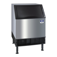
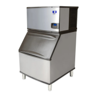
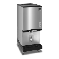
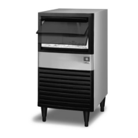
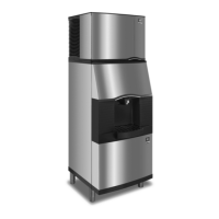
Lists all supported ice machine models.
Explains the components of an ice machine model number.
Details warranty coverage for ice machines.
Lists items not covered by the ice machine warranty.
Outlines warranty coverage for residential use.
Specifies what the limited warranty does not cover.
Criteria for selecting an appropriate installation location.
Specifies required clearances around the ice machine.
Provides heat rejection data for different models.
Step-by-step guide on how to properly level the ice machine.
Details voltage, fuse, and ampacity requirements for installation.
Provides electrical specifications for air-cooled models.
Provides electrical specifications for water-cooled models.
Covers water supply and drain connections for the ice machine.
Guidelines for installing drain lines to prevent backflow.
Information specific to water-cooled models using cooling towers.
Table detailing water supply and drain line sizing requirements.
Procedure for cleaning and sanitizing the ice machine interior.
Explains the function and operation of the touch pad controls.
Instructions on how to remove specific parts for cleaning.
Procedure for cleaning between regular sanitizing cycles.
Guidelines for inspecting the ice machine for proper function.
Steps for cleaning the condenser to ensure efficient operation.
Procedure for taking the ice machine out of service or winterizing it.
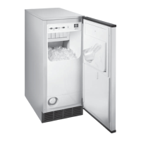
Instructions on how to remove the ice storage bin.
Describes the functions of the touch pad buttons and lights.
Explains how to start and stop ice making using the On/Off button.
Details how to use the delay start feature for the ice machine.
Instructions on initiating and managing the cleaning cycle.
Indicates the function of the bin full indicator light.
Explains the meaning of the service indicator light.
Describes the step-by-step process of ice making.
Explains the operation of the water assist harvest cycle.
Details the various timers and their functions on the control board.
Information on built-in safety limits that stop the machine.
A chart showing energized parts during the ice making sequence.
Procedures for checking ice thickness and making adjustments.
Table showing minimum and maximum ice slab weights per cycle.
How to enter and use the control board test mode.
Procedure for operating the machine without bin and touch pad.
Troubleshooting steps for a machine that fails to start.
Diagnosing issues with harvest cycle initiation related to the float switch.
Troubleshooting when harvest cycle starts too early.
Procedure for checking and calculating ice production rates.
Checklist for visual inspection during installation.
Checklist for diagnosing water system related problems.
Analysis of ice formation patterns for diagnostic purposes.
Explains safety limits that stop the machine to prevent component failure.
Checklist to help diagnose issues related to Safety Limit #1.
Details issues related to Safety Limit #2 (harvest time exceeded).
Details issues related to Safety Limit 3 (freeze time without water).
Procedure for analyzing discharge pressure in the refrigeration system.
Procedure for analyzing suction pressure in the refrigeration system.
General information and normal operation of the harvest valve.
Analysis of potential harvest valve failure modes.
Procedure for comparing evaporator inlet and outlet temperatures.
How to analyze discharge line temperature for diagnostics.
Introduction to tables for diagnosing refrigeration components.
Interpreting diagnostic results to identify the refrigeration problem.
Function, specifications, and check procedure for the main fuse.
Function, operation, and check procedure for the bin switch.
Function and checks for normal operation of the touch pad.
Function and checks for the ice thickness and harvest float switches.
Procedures for diagnosing compressor electrical issues.
Function and checks for the fan cycle control.
Function and checks for the high pressure cutout control.
Information on the liquid line filter drier and its replacement.
Definitions and procedures for refrigerant recovery and evacuation.
Manitowoc's policy on refrigerant handling, re-use, and disposal.
General procedures for refrigerant recovery and recharging.
Specific recovery and evacuation procedures for self-contained units.
Requirements for restoring contaminated refrigeration systems.
Steps for cleaning systems with mild contamination.
Steps for cleaning systems with severe contamination.
Procedure for replacing controls without releasing refrigerant.
Table listing refrigerant charge amounts for different models.
Guidelines for verifying ice machine operation using charts.
Performance data for U0140 air-cooled models.
Performance data for U0140 water-cooled models.
Performance data for U0190 air-cooled models.
Performance data for U0240 air-cooled models.
Performance data for U0240 water-cooled models.
Performance data for U0310 air-cooled models.
Performance data for U0310 water-cooled models.
Contains electrical wiring diagrams for various models.
Specific wiring diagram for U140, U190, and U240 models.
Diagram showing the layout and connections on the electronic control board.
Tubing schematic for the U0140 model.
Tubing schematic for U0190, U0240, and U0310 models.
| Model | STH042 7/15 |
|---|---|
| Ice Type | Half Dice |
| Voltage | 115 V |
| Condenser Type | Air-Cooled |
| Water Connection | 3/8" FPT |
| Refrigerant | R-404A |
| Frequency | 60 Hz |
| Phase | 1 |