5
4. Preparation
• In order to ensure a stable working procedure during the lling process, the ll station
should be secured with screws or another connector to a table or wall.
• Connect the lling hose by means of a compressed air source (compressor or air tank)
by inserting the hose into one of the two 5.8” HP ports. Ensure that the other one remains
closed.
• The compressed air may be fed into the ll station through two 5.8” HP ports at the same
or through a series connection or more than one ll station.
• By the opening of an appropriate outlet in the air reservoir or in the compressor,
the lling station is supplied with compressed air, the pressure gauge in the ll station
will show the current operational pressure.
• After following the above steps, the ll station is ready to use.
5. Filling the Bottle
• Connect the bottle by using the female quick release coupler with the lling hose.
• Then open the lever valve of the ll station.
• Wait until the pressure in the bottle has reached the desired level.
• Close the lever valve afterwards, whereby the lling hose is automatically vented.
• Disconnect the female quick release coupler from the bottle.
The manufacturer takes NO responsibility for damage which happens
by not paying attention to the above instructions!
6. Technical Documentation, Description of Parts. FPS-3000
The construction of the ll station FPS-3000 will be outlined in this section.
The directory and main components are listed here.
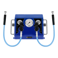
The following basic components of the air ll station are shown in Figure 1:
Casing of the lling station with elements of the pneumatic installation (1),
lever valve ZD-3500 (2) and lling hose with female quick release coupler (3)
for the bottle connection.
USER MANUAL / FPS-3000 / FPD-3000 / © 2018 MANTA / All rights reserved.