Do you have a question about the Marantz 1152DC and is the answer not in the manual?
Adjusts DC offset for left and right channels to 0mV (±5mV) using VTVM.
Lists essential test equipment and their uses for servicing the amplifier.
Illustrates how to set the plug for different voltage operations (110-240V).
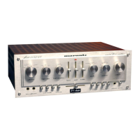
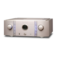
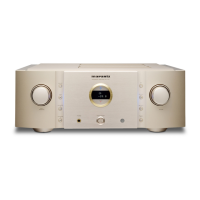
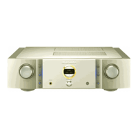
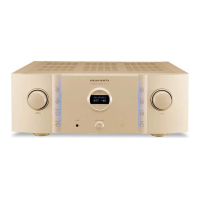
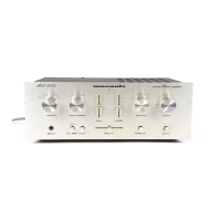
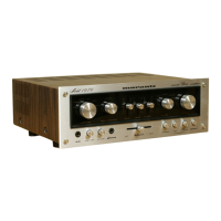
Identifies components and adjustment points on the amplifier's front panel.
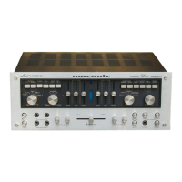
Locates major components on the top side of the main amplifier chassis.
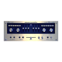
Identifies components and adjustment points on the amplifier's rear panel.
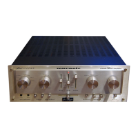
Locates major components on the bottom side of the main amplifier chassis.
Provides the schematic diagram and component layout for the Filter Amplifier Assembly (PH01).
Shows the schematic diagram and component locations for the Pre-Amplifier Assembly (PJ01).
Details the schematic diagram and component layout for the Speaker Switch Assembly (PW00).
Presents the schematic diagram and component locations for the Front Panel Assembly (PS00).
Provides the schematic diagram and component locations for the Main Amplifier Assembly (P700).
Details the schematic diagram and component layout for the Relay Assembly (PNOO).
Shows the schematic diagram and component locations for the Rear Panel Assembly (PV00).
Shows the breakdown and assembly of the amplifier's cabinet components.
Details the exploded view and part identification for the amplifier's chassis.
Illustrates the exploded view of the rear panel for US and Canadian models.
Illustrates the exploded view of the rear panel for European models.
Detailed technical specifications for the amplifier section of the US model.
Detailed technical specifications for the preamplifier section of the US model.
General technical specifications including power, dimensions, and weight for the US model.
Detailed technical specifications for the audio section of the European model.
General technical specifications including power, dimensions, and weight for the European model.
| Power Output | 76 watts per channel into 8Ω (stereo) |
|---|---|
| Frequency Response | 10Hz to 60kHz |
| Total Harmonic Distortion (THD) | 0.1% |
| Total harmonic distortion | < 0.03% |
| Damping Factor | 100 |
| Input Sensitivity | 0.18mV (MC), 1.8mV (MM), 180mV (line) |
| Signal to noise ratio | 76dB (MC), 86dB (MM), 94dB (line) |
| Channel Separation | 55dB (MM), 55dB (line) |
| Dimensions | 17.5 x 5.25 x 14.5 inches |
| Weight | 35 lbs |
| Speaker load impedance | 4Ω to 16Ω |
| Type | Stereo Amplifier |