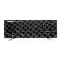
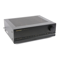
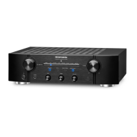
The Marantz PM-66SE F (also known as 74PM66/11B/12B/15B) is an integrated stereo amplifier. This service manual provides comprehensive information for its maintenance and repair, ensuring the unit continues to perform to its original specifications.
Function Description:
The PM-66SE F is designed to amplify audio signals from various sources, delivering high-quality stereo sound through connected speakers. It features multiple input options, including a magnetic cartridge input for turntables, as well as Tuner, CD, Aux, and Tape inputs. The amplifier incorporates a power amplifier section, a pre-amplifier with tone controls (Balance and Master Volume), and a dedicated phono amplifier. A microprocessor (U-PROC) is integrated for system control, likely managing input selection, volume, and other operational parameters, including an infrared (IR) receiver for remote control functionality. The unit also includes a headphone output for private listening. Power is supplied via a transformer, followed by a discrete voltage regulator for stable operation. Speaker protection circuitry is also present to safeguard connected speakers from potential damage.
Important Technical Specifications:
- Power Output:
- RMS (8 ohms / 4 ohms): 50/70W
- DIN (8 ohms / 4 ohms): 55/75W
- IHF Dynamic Power:
- (8 ohms / 4 ohms): 80/110W
- Total Harmonic Distortion (THD) at 8 ohms rated output: 0.008%
- Intermodulation Distortion: 0.008%
- Damping Factor: 100
- Magnetic Cartridge Input:
- Input Sensitivity/Impedance: 2.5 mV / 47 k ohm
- Accuracy of Frequency Response to IEC RIAA: 0.5 dB
- Signal to Noise Ratio (IHF A weighted): 87 dB
- Tuner/CD/Aux/Tape Inputs:
- Input Sensitivity/Impedance: 150 mV / 33 k ohm
- Signal to Noise Ratio (A weighted): 97 dB
- Frequency Response (-3 dB limits): 5 Hz - 70 kHz
- Channel Separation (1 kHz / 10 kHz): > 85 dB / 65 dB
- General:
- Power Requirements:
- /12, /15 versions: 230 V AC, 50 Hz
- /11 version: 110/120/220/240 V AC, 50/60 Hz
- /F version: 100 V AC, 50/60 Hz
- Dimensions (MAX):
- Width: 439 mm
- Height: 138 mm
- Depth: 343 mm
- Weight (Unit alone): 6.7 kg
Usage Features:
The amplifier is designed for straightforward operation. Users can select various audio sources via a selector switch, including Phono, CD, Tuner, and Aux. Tape monitoring and copying functions are also available. The unit features standard balance and master volume controls for audio adjustment. The inclusion of an IR receiver indicates remote control capability, enhancing user convenience. Different power requirement versions (/12, /15, /11, /F) cater to various regional electrical standards, with a voltage selector for the /11B version to adapt to different power source voltages (120V, 240V, 110V, 220V).
Maintenance Features:
The service manual provides detailed instructions and diagrams essential for maintenance and repair.
- Idling Current Adjustment: A critical maintenance procedure involves adjusting the idling current for both the left (L CH) and right (R CH) channels. This process requires setting the Master Volume to minimum, Balance to center, and semi-fixed resistors R755 (L CH) and R756 (R CH) on PCB P701 to their center positions. A digital voltmeter is then used to measure the DC voltage across specific test points on cement resistors R767 or R768, with the target setting value being 14 mV (38.9mA) after the unit has been powered on for more than 6 minutes. This adjustment is crucial for optimal amplifier performance and longevity.
- Voltage Conversion: For the /11B version, the manual details how to convert the unit to a different power source voltage by changing the position of a voltage selector. A caution emphasizes disconnecting the power supply cord before performing this conversion.
- Test Equipment Required: A comprehensive list of test equipment is provided, including a Distortion Analyzer, Audio Oscillator, ACVTVM, Oscilloscope, Circuit Tester, DCVTVM, AC Wattmeter, Line Voltmeter, Variable Autotransformer, and Shorting Plug. Each item's specific use in servicing, such as distortion measurements, waveform analysis, troubleshooting, and voltage measurements, is outlined.
- Diagrams and Lists: The manual includes a block diagram, wiring diagram, schematic diagrams with parts locations (pattern side), exploded views, and detailed parts lists (including electrical parts, common parts codes, and fusible resistor information). These resources are invaluable for identifying components, tracing signal paths, and performing accurate repairs.
- Safety Notes: Important safety warnings are highlighted, particularly regarding fire and electrical shock hazards. It is emphasized that only original parts should be used to replace components marked with a safety symbol (triangle with exclamation mark), as substitutions may increase risk. A "Shock, Fire Hazard Service Test" is also outlined, requiring resistance measurement between AC cord connector pins and the unit's metal parts to ensure safety before returning the appliance to the customer.
- Parts Ordering: The manual details the procedure for ordering parts, including required information such as complete address, part numbers, quantities, descriptions, model number, and preferred shipment method. It also lists Marantz subsidiaries and agents globally for parts availability.