Explanatory Photos for DISASSEMBLY
• For the shooting direction of each photos used in this manual, see the photo below.
• A, B, C and D in the photo below indicate the shooting directions of photos.
• The photographs with no shooting direction indicated were taken from the top of the unit.
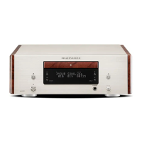
• Photos of HD-CD1 N1B are used in this manual.
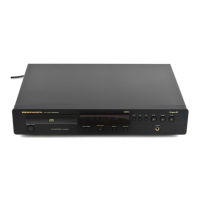
The viewpoint of each photograph
(Shooting direction : X) [View from the top]
Front side
↑Shooting direction: A↑
↓Shooting direction: B↓
↓Shooting direction: D↓
↑Shooting direction: C↑
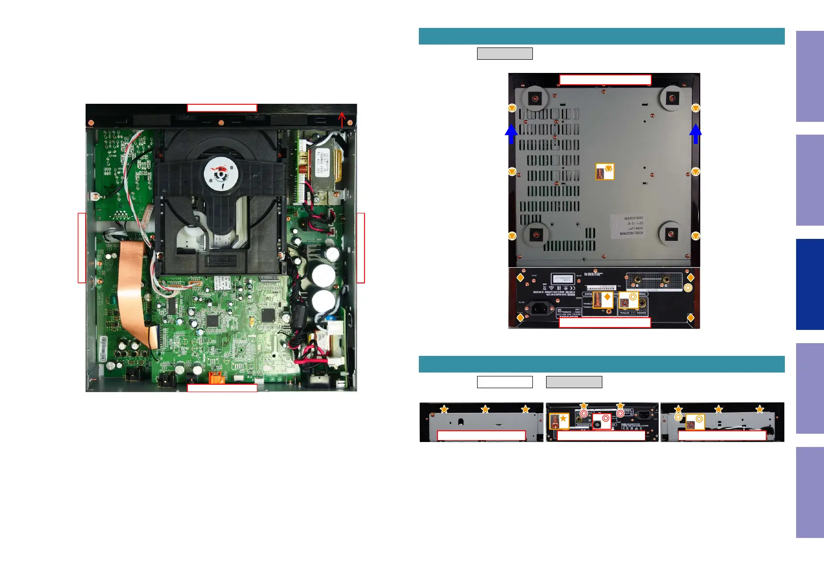
Proceeding : SIDE PANEL
(1) Remove the screws.
Proceeding : SIDE PANEL → TOP CABINET
(1) Remove the screws.
1. SIDE PANEL
↑Shooting direction: A↑
View from the bottom
x4
x1
x6
2. TOP CABINET
↑Shooting direction: A↑↑Shooting direction: D↑ ↑Shooting direction: C↑
x8
x1
x2
22
Caution in
servicing
Electrical Mechanical Repair Information Updating
 Loading...