3
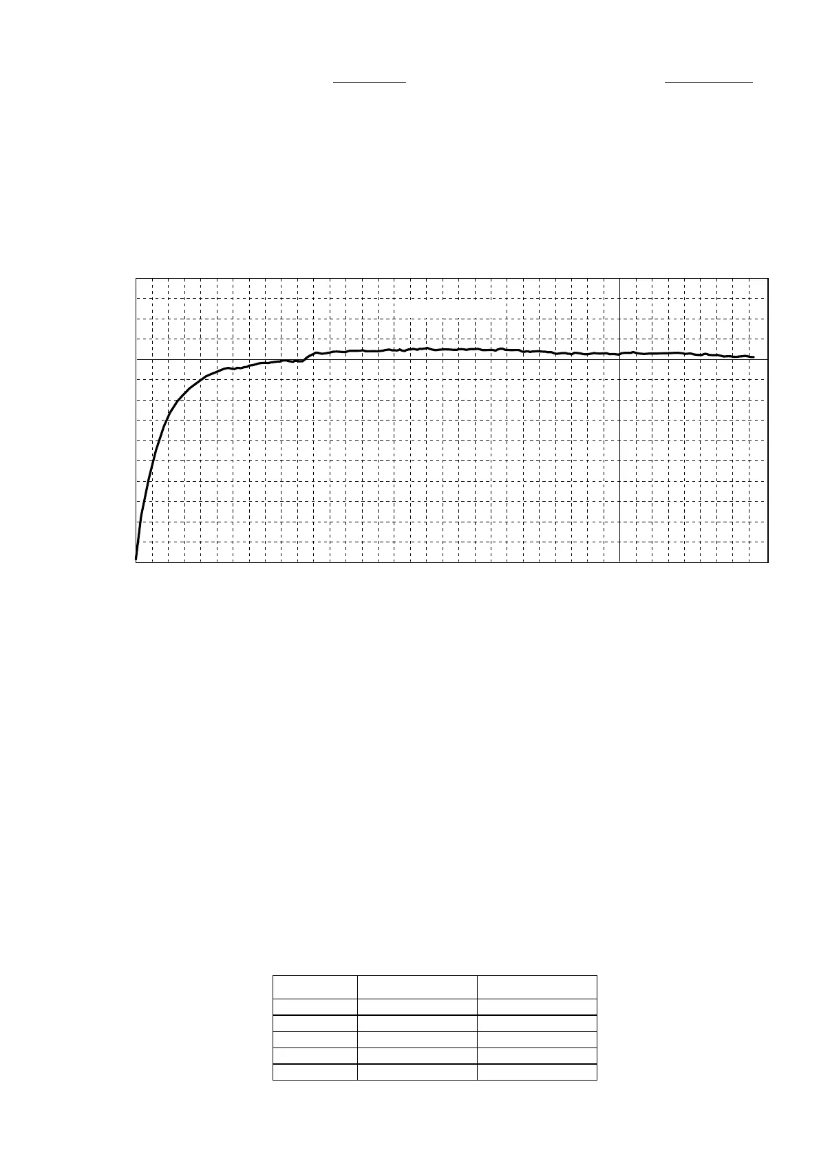
4. The voltage of the idling current will be 10mV(50mA) for
each.
The current value is stabilized by about 10mV (50mA) in
about 30 minutes after turn on power.
Refer to the following graph for the idling current and time
after turn on power.
5. 3 minutes after turn on power, adjust the idling current to
8mV (40mA), after 10 minutes, it checks becoming the
value of about 10mV (50mA).
Meter Adjustment
1. Connect an oscillator to the input terminal
UNBALANCED-1 and connect an AC voltage meter to
the speaker output terminals. ATTENUATOR is set to 0dB
and no load is connected to the speaker output.
Turn the variable resister R917 on the PWB (P801)
counterclockwise to the end.
2. Turn on power and adjust output power (output frequency
1kHz) of the oscillator to set the speaker output voltage to
15.5V.
3. When the speaker output voltage becomes 15.5V, adjust
the variable resistor R917 on the PWB P801 to set the
meter -10dB. (Output voltage 15.5V means 30W for 8Ω,
60W for 4Ω.)
4. Assuming this point as 0db, decrease the output power of
the oscillator like 0dB → –20dB → –30dB→ –40dB, the
meter will show the corresponding
4. アイドリング電流の設定値はそれぞれ10mV(50mA)とし
ます。
電源投入後約30分で約10mV(50mA)で安定します。
電源投入後のアイドリング電流と時間経過の推移は下記グ
ラフを参照してください。
5. 調整は、電源を投入し3分後に8mV(40mA)に調整し、さ
らに
10分後に10mV(50mA)前後の値になることを確認し
てください。
メーター調整
1. 入力端子UNBALANCED-1に発振器を接続し、スピーカー
出力端子に
ACボルトメーターを接続します。
ATTENUATORは0dB、スピーカー出力は無負荷とします。
P801基板の半固定抵抗R917は反時計方向に絞り切った状
態にしてください。
2. 電源をONしスピーカー出力電圧が15.5Vになるように発振
器の出力レベルを調整(周波数は
1kHz)してください。
3. スピーカー出力電圧が15.5Vになったら、メーターが-
10dB
を指すようにP801基板の半固定抵抗R917を調整しま
す。(出力電圧
15.5Vは8Ω時30W、4Ω時60Wの電圧にな
ります。)
4. この状態を-10dBとして発振器の出力レベルを0dB →
-20dB → -30dB → - 40dBと順に減衰させていくと、メー
ターの針はスケール板のそれぞれの表示値を示します。
METER 8 OHM LOAD 4 OHM LOAD
0 dB 300 W 600 W
-10 dB 30 W 60 W
-20 dB 3 W 6 W
-30 dB 0.3 W 0.6 W
-40 dB 0.03 W 0.06 W
0 5 10 15 20 25 30 35
2
(10)
4
(20)
6
(30)
8
(40)
10
(50)
12
(60)
mV
(mA)
(minutes)
Idling Current