23 24
1. DC offset adjustment
Master Volume : Minimum, Speaker out : non Load
Step Power Channel
Adjustment
Point
Test Point Adjustment Vaule
Front L R715
Center RT15
Front R RP16
Surr. L RP15
1on
Surr. R R716
Speaker Output
Terminal
20mV
±
Note : If the measured value is not exceed ±20mV, no need to adjust the DC offset.
2. Iding current adjustment
Master Volume : Minimum, Speaker out : non Load
Step Power
Channel
Adjustment
Point
Test Point
Adjustment
Vaule
Front L R743 J713 or R773
Center RT43 JT13 or RT73
Front R RP44 JP04 or RP74
1 Power on
Surr. L RP43 JP03 or RP73
within 1 minute
0.4mV
Surr. R R744 J714 or R774
2
after
4 minutes
J***:4P Connecter
(between 1p-4p)
R***:Emitter Resister
(0.1ohms x2)
see table
for adjustment
vaule
Time since power on Idling current adjust. Time since power on Idling current adjust.
4–4 minutes 30 seconds 5.6mV 11-12 minutes 8.0mV
4m30s–5 minutes 6.4mV 12-14 minutes 7.6mV
5–5 minutes 30 seconds 7.2mV 14-16 minutes 7.2mV
5m30s–6 minutes 7.7mV 16-18 minutes 6.5mV
6–7 minutes 8.2mV 18-22 minutes 5.6mV
7-8 minutes 8.6mV 22-26 minutes 4.9mV
8-9 minutes 8.8mV 26-30 minutes 4.4mV
9-10 minutes 8.6mV more than 30 minutes 4.0mV
10-11 minutes 8.4mV The taget is 4.0mV
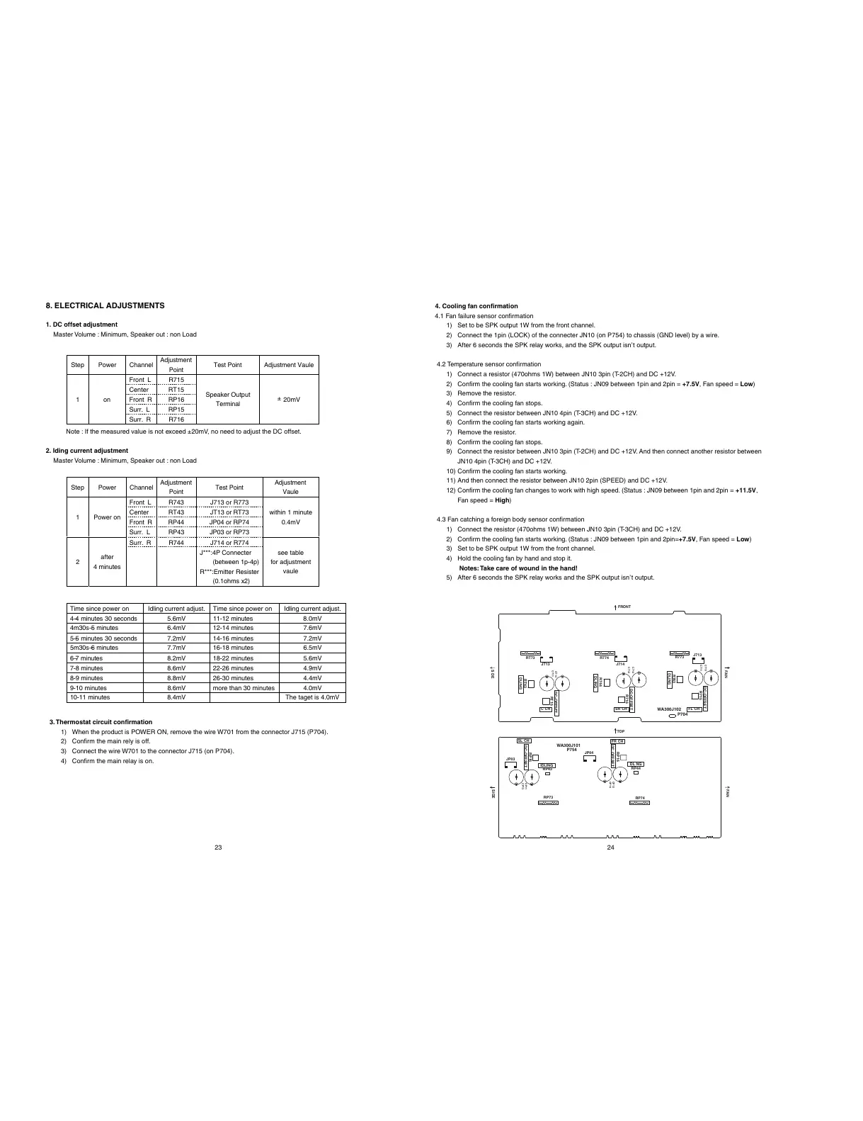
3. Thermostat circuit confirmation
1) When the product is POWER ON, remove the wire W701 from the connector J715 (P704).
2) Confirm the main rely is off.
3) Connect the wire W701 to the connector J715 (on P704).
4) Confirm the main relay is on.
8. ELECTRICAL ADJUSTMENTS 4. Cooling fan confirmation
4.1 Fan failure sensor confirmation
1) Set to be SPK output 1W from the front channel.
2) Connect the 1pin (LOCK) of the connecter JN10 (on P754) to chassis (GND level) by a wire.
3) After 6 seconds the SPK relay works, and the SPK output isn’t output.
4.2 Temperature sensor confirmation
1) Connect a resistor (470ohms 1W) between JN10 3pin (T-2CH) and DC +12V.
2) Confirm the cooling fan starts working. (Status : JN09 between 1pin and 2pin = +7.5V, Fan speed = Low)
3) Remove the resistor.
4) Confirm the cooling fan stops.
5) Connect the resistor between JN10 4pin (T-3CH) and DC +12V.
6) Confirm the cooling fan starts working again.
7) Remove the resistor.
8) Confirm the cooling fan stops.
9) Connect the resistor between JN10 3pin (T-2CH) and DC +12V. And then connect another resistor between
JN10 4pin (T-3CH) and DC +12V.
10) Confirm the cooling fan starts working.
11) And then connect the resistor between JN10 2pin (SPEED) and DC +12V.
12) Confirm the cooling fan changes to work with high speed. (Status : JN09 between 1pin and 2pin = +11.5V,
Fan speed = High)
4.3 Fan catching a foreign body sensor confirmation
1) Connect the resistor (470ohms 1W) between JN10 3pin (T-3CH) and DC +12V.
2) Confirm the cooling fan starts working. (Status : JN09 between 1pin and 2pin=+7.5V, Fan speed = Low)
3) Set to be SPK output 1W from the front channel.
4) Hold the cooling fan by hand and stop it.
Notes: Take care of wound in the hand!
5) After 6 seconds the SPK relay works and the SPK output isn’t output.
C711
C713
C714
C712
CT13
CT11
CP12
CP14
CP11
CP13
R715
J713
R773
R743
R774
J714
R716
R744
RT15
RT43
RT73
JT13
RP44
RP74
RP16
JP04
RP43
RP73
RP15
JP03
P704
FL CHSR CHCCH
P754
SL CH
FR CH
DC-OFFSET
DLING
DC-OFFSET
DLING
DC-OFFSET
DLING
DL NG
DC OFFSET
IDLING
DC-OFFSET
FAN
FAN
SIDE
SDE
FRONT
TOP
WA300J102
WA300J101
 Loading...