Do you have a question about the Marantz PM-KI-PEARL-LITE and is the answer not in the manual?
| Damping factor | 100 |
|---|---|
| Amplifier class | - |
| Frequency range | 5 - 100000 Hz |
| Input sensitivity | 2 mV |
| Audio output channels | 2.0 channels |
| Peak power per channel | 100 W |
| Signal-to-Noise Ratio (SNR) | 106 dB |
| Total Harmonic Distortion (THD) | 0.0002 % |
| RMS power output per channel (8 Ohm) | 70 W |
| Pre out port | Yes |
| Audio (L/R) in | 6 |
| Audio (L/R) out | 2 |
| Headphone outputs | 1 |
| Speakers connectivity type | RCA |
| Purpose | Home |
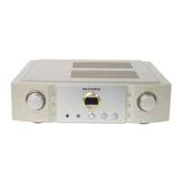
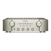
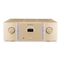
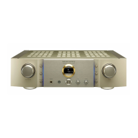
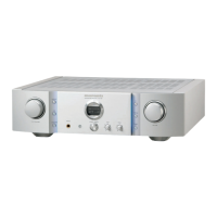
| Product color | Gold, Silver |
| Volume control | Rotary |
| Cables included | AC |
| Connectivity technology | Wired |
| Built-in display | No |
| Power consumption (standby) | 0.3 W |
| Power consumption (typical) | 200 W |
| Depth | 379 mm |
|---|---|
| Width | 440 mm |
| Height | 129 mm |
| Weight | 12000 g |
Mandatory safety test procedure after servicing to prevent electrical hazards.
Procedure to check for electrical leakage before returning the unit to the customer.
Identification and importance of safety-critical parts in the unit.
Detection of abnormalities in the Power Amplifier section by PROT-1 signal.
Detection of abnormalities in the power supply circuit by PROT-2 signal.
Diagnosing issues when the unit does not power on and the standby LED is off.
Diagnosing issues when the unit does not power on and the standby LED flashes.