EasyManua.ls Logo

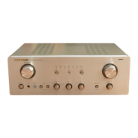
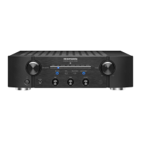
Marantz PM7000/N1B User Manual

Marantz PM7000/N1B
29 pages
To Next Page IconTo Next Page
Page #1 background imageLoading...
Page #1 background image
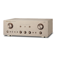
Integrated amplifier
TABLE OF CONTENTS
SECTION PAGE
1. SPECIFICATIONS ...................................................................................................................................... 1
2. TEST EQUIPMENT REQUIRED SERVICING ........................................................................................... 2
3. IC INFORMATIONS.................................................................................................................................... 3
4. BLOCK DIAGRAM ...................................................................................................................................... 5
5. WIRING DIAGRAM..................................................................................................................................... 7
6. SCHEMATIC DIAGRAM AND PARTS LOCATION (PARTS SIDE) ........................................................... 9
7. EXPLODED VIEW AND PARTS LIST ...................................................................................................... 33
8. IDLING CURRENT AND DC OFFSET VOLTAGE ALIGNMENT ............................................................. 34
9. ELECTRICAL PARTS LIST ...................................................................................................................... 35
Service
Manual
PM7000 /N1B, /N1G, /U1B
PM8000 /N1B, /N1G, /F1B, /F1N
Please use this service manual with referring to the user guide (D.F.U) without fail.
R
- PM7000 / PM8000 -
276W855010 ACT
3120 785 22011
First Issue:1999.09
PM7000/8000
Question and Answer IconNeed help?

Do you have a question about the Marantz PM7000/N1B and is the answer not in the manual?

Marantz PM7000/N1B Specifications

General IconGeneral
BrandMarantz
ModelPM7000/N1B
CategoryAmplifier
LanguageEnglish

Summary

Service and Support Information

Ordering Parts and Contact Details

Provides Marantz subsidiary/agent contacts for ordering parts and service inquiries.

Critical Service Safety Warning

Important safety test procedure before returning the unit to the customer.

Technical Specifications

Power Output Ratings

Details output power for Class AB and Class A operations, plus dynamic power.

Input and Response Characteristics

Covers input sensitivity, impedance, frequency response, and S/N ratio.

General Unit Dimensions and Requirements

Includes power requirements, physical dimensions, and weight.

Servicing Equipment and Procedures

Required Test Equipment

Lists necessary test equipment and their applications for maintenance.

Idling Current and DC Offset Alignment

Procedures for adjusting quiescent current and DC offset voltage.

IC Information

Microprocessor Block Diagram

Shows the internal structure of the TMP47C200BM microprocessor.

Microprocessor Pin Functions

Details the function of each pin on the TMP47C200BM microprocessor.

System Diagrams

Audio Signal Flow Diagram

Illustrates the path of audio signals through the amplifier's sections.

Wiring Diagrams

Details wiring for main power, volume, inputs, outputs, and speakers.

Schematic Diagrams

Provides schematics for function selection and tape interface circuits.

Component Identification

Exploded View of Components

Visual representation of the unit's physical assembly and parts.

Electrical Parts List (Overview & Common Parts)

Introduces the parts list and details common components.

Resistors, Capacitors, and Semiconductors

Detailed lists of resistors, capacitors, semiconductors, and ICs with part numbers.

Circuit Board Specific Components

Lists components for specific circuit boards like Tone, Front, and SPK SW.

Related product manuals