57
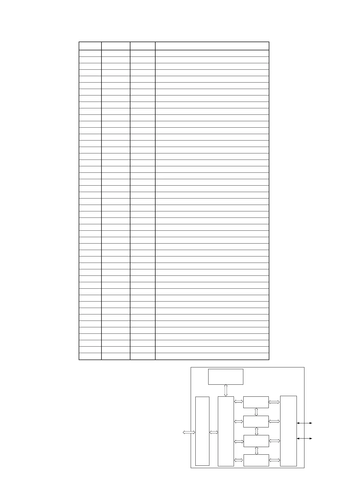
Pin No. Name I/O Description
1 PVDD PWR Power supplier for storage device interface
2 D8 I/O Storage device data bus bit 8*
3 D9 I/O Storage device data bus bit 9*
4 D10 I/O Storage device data bus bit 10*
5 D11 I/O Storage device data bus bit 11*
6 PGND PWR Ground for storage device interface
7 D12 I/O Storage device data bus bit 12*
8 D13 I/O Storage device data bus bit 13*
9 D14 I/O Storage device data bus bit 14*
10 D15 I/O Storage device data bus bit 15*
11 DIOR# O Storage device read strobe signal*
12 DIOW# O Storage device write strobe signal*
13 INTRQ I Storage device interrupt request signal*
14 DVDD PWR 5V power supplier for internal logic
15 DGND PWR Ground for internal logic
16 Crystal out CLK Crystal clock output
17 Crystal in CLK Crystal clock input
18 GPIO1 I/O General purpose I/O 1
19 GPIO2 I/O General purpose I/O 2
20 V3.3 USB 3.3v power supplier for USB bus
21 D+ USB D+ signal for USB
22 D- USB D- signal for USB
23 AVDD PWR 5V power supplier for USB interface
24 AGND PWR Ground for USB interface
25 GPIO3 I/O General purpose I/O 3
26 GPIO4 I/O General purpose I/O 4
27 TSTMODE I Used at test mode only
28 EXTRST# I Used at test mode only
29 GPIO8 I/O General purpose I/O 8
30 GPIO7 I/O General purpose I/O 7
31 GPIO6 I/O General purpose I/O 6
32 GPIO5 I/O General purpose I/O 5
33 DGND PWR Ground for internal logic
34 DVDD PWR 5V power supplier for internal logic
35 CS3FX# O Storage device register bank 3 selector*
36 CS1FX# O Storage device register bank 1 selector*
37 A0 O Storage device address bus bit 0*
38 A1 O Storage device address bus bit 1*
39 A2 O Storage device address bus bit 2*
40 D0 I/O Storage device data bus bit 0*
41 D1 I/O Storage device data bus bit 1*
42 D2 I/O Storage device data bus bit 2*
43 D3 I/O Storage device data bus bit 3*
44 PGND PWR Ground for storage device interface
45 D4 I/O Storage device data bus bit 4*
46 D5 I/O Storage device data bus bit 5*
47 D6 I/O Storage device data bus bit 6*
48 D7 I/O Storage device data bus bit 7*
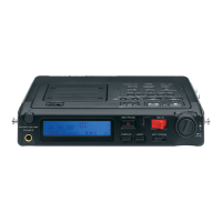
Micro-
controll er
USB
Registers
&
FIFO
Control
Endpoint 0
Control
8 Bytes FIFO
Endpoint 1
Bulk IN
64 Bytes FIFO
USB
Interface
D+
D-
Endpoint 2
Bulk OUT
64 Bytes FIFO
Endpoint 3
Interrupt IN
8 Bytes FIFO
ATA
ATAPI
CF
Interface
ATA
* Output voltage of this pin is equivalent to voltage supplied by PVDD.
Input voltage of this pin can be from 0v to 5v, and it threshold is 1v ~ 2v.
Therefore, these pins can support 3v/5v interface according to voltage of
PVDD.
QX01 : GL641USB (USB DRIVER)