Do you have a question about the Marantz PMD670/W1B and is the answer not in the manual?
| Recording Format | MP3, WAV |
|---|---|
| Sample Rate | 44.1 kHz, 48 kHz |
| Headphone Output | 1/4" Stereo Jack |
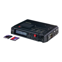
| Type | Portable Digital Recorder |
| Recording Media | Compact Flash |
| Bit Rate | 16-bit, 24-bit |
| Inputs | XLR, 1/4" TRS |
| Outputs | RCA |
| Power Supply | AC Adapter, AA Batteries |
Instructions and requirements for ordering original Marantz replacement parts.
Details safety test procedures and precautions after servicing the appliance.
Details technical specs for media, recording, bit rates, sampling, and frequency response.
Covers power, dimensions, weight, accessories, and audio connections.
Procedure to reset all settings to default status.
Steps to check firmware version and CompactFlash speed.
Instructions on removing screws and the battery cover for initial access.
Instructions on removing screws securing the side panels.
Instructions on removing screws securing the side panels.
Instructions for disconnecting connectors and removing the top case.
Instructions on removing the side panel of the Audio I/O side.
Instructions for removing internal panels and the main PCB.
Lists required equipment and connection steps for DSP firmware update.
Step-by-step guide for performing the firmware update on the DSP.
Instructions for completing the update, disconnecting, and verifying.
Lists required hardware and software for updating the microprocessor firmware.
Guides on how to install the update software on the PC.
Steps for installing and configuring the FLASH2 software.
Steps to select CPU type and verification method in FLASH2.
Configures communication parameters like transfer rate and COM port in FLASH2.
Steps to set terminal state and write firmware to the microprocessor.
Details the process of uploading and verifying the firmware.
Visual guides showing the location of various components and PCBs on the unit.
Detailed layout diagrams showing component placement on the PM01 A PCB.
Detailed layout diagrams showing component placement on the PM01 B PCB.
Detailed pin assignments and functions for the QU01 microprocessor.
Pin assignments and functions for various integrated circuits.
Pin assignments and functions for the QX01 USB driver IC.
Pin assignments and functions for the Q401 AK4114 DIT IC.
Further pin assignments and functions for the Q401 AK4114 DIT IC.
Pin assignments and functions for the Q402 AK5380VT ADC IC.
Pin assignments and functions for the Q403 AK4380VT-E2 DAC IC.
Pin assignments and functions for the QP01 CPLD and memory ICs.
Pin assignments and functions for buffer ICs like MC74LVX245DT and MC74LVX541DT.
Detailed data for multiplexer ICs like TC74HC4052AFT and TC74HC4053A.
Pin assignments and functions for the Q819 power management IC.
Pin assignments and functions for voltage regulator and LCD driver ICs.
Descriptions of signals related to the DSP, including their functions and assignments.
Visual representation showing the assembly of the main unit with part locations.
A detailed list of parts for the main unit, including part numbers and descriptions.
Lists resistors, capacitors, fuses with codes, values, and specifications.
Information regarding fuse replacement, safety precautions, and abbreviations.
Lists electrical components for the audio I/O circuit and various resistors.
Extensive list of capacitors used in the device, categorized by type and value.
Further entries for various capacitors, including electrolytic and ceramic types.
Further listings of capacitors and connector parts for the device.
Comprehensive list of resistors, including their part numbers and specifications.
Further resistor entries, detailing values, tolerances, and part numbers.
Further resistor listings and parts for EMI filters.
Lists of diodes and transistors used in the device, with part numbers.
Additional listings for transistors and integrated circuits.
Further listings for ICs and crystal components.
Detailed data for multiplexer ICs like TC74HC4052AFT and TC74HC4053A.
Pin assignments and functions for the Q819 power management IC.
Pin assignments and functions for voltage regulator and LCD driver ICs.
Descriptions of signals related to the DSP, including their functions and assignments.