Hardware Software Interface (HSI) Page: 3 / 17
SW-A0441-HSI-002 Document Version [1.00b]
Marantz America, Inc. 2007
All rights are reserved. Reproduction in whole or in part is prohibited without the written consent of copyright.
All specifications might be subject to change without notice.
1. Introduction
1-1. Purpose
This document was written in order to clarify specification for control this product by the host controller.
1-2. Scope
This document would be using by software or hardware engineers for production of this product.
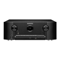
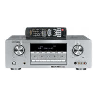
This product is [marantz SR6400/SR5400]. (It’s refered to as “This product” after this.)
1-3. Abbreviations
Abbreviation Description
1-4. References
2. Global Description
2-1. Overview
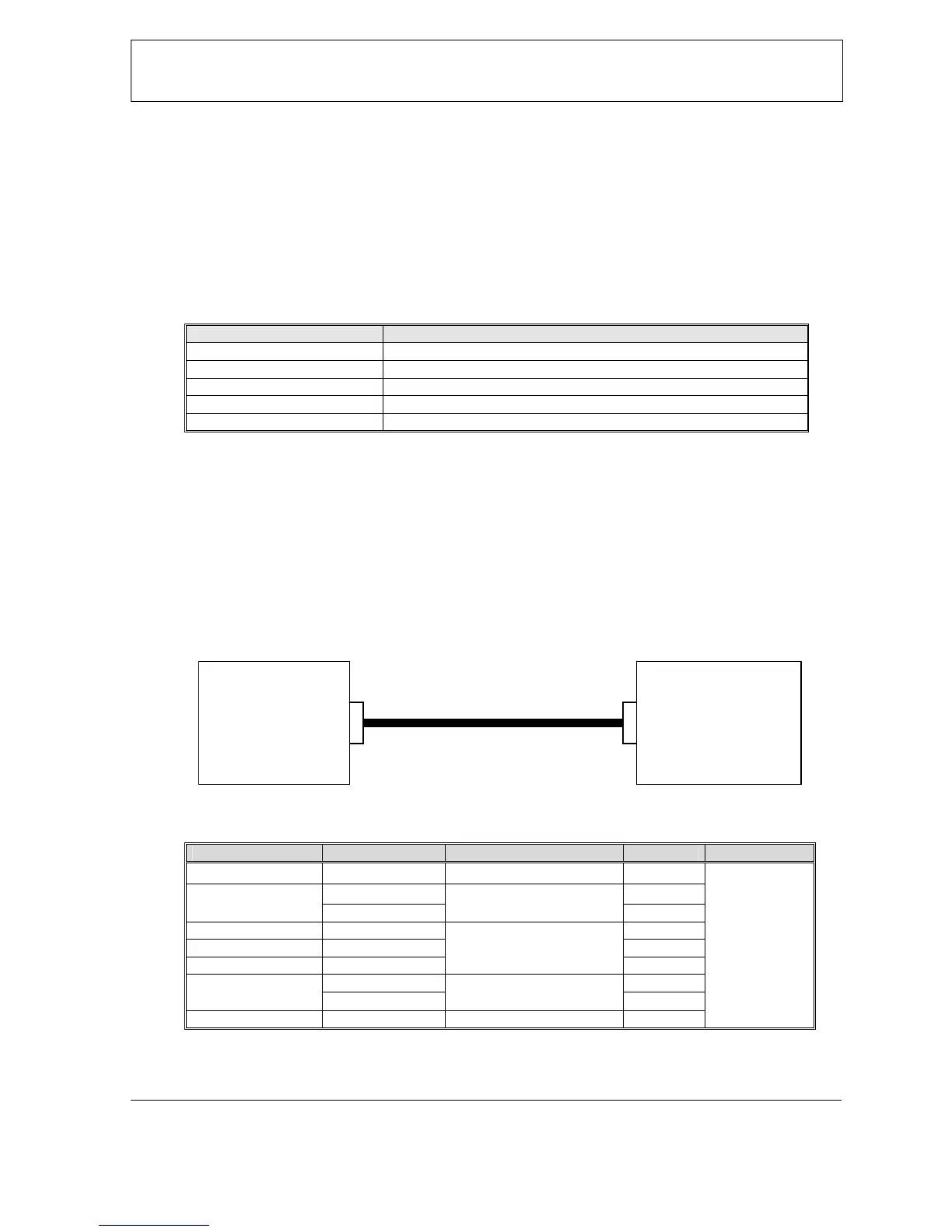
A Host controller can control or watch out This product as a Slave very easily via the communication cable.
2-2. Block Diagram
2-3. Interface connecter specification of This Product
Processor Interface Signal name Connection device D-Sub Pin Connecter
- N.C. - 1
TxD (output) 2 UART
RxD (input)
RS232C Level shift driver
3
- N.C. 4
- GND 5
- N.C.
-
6
CTS (input) 7 GENERAL PORT
RTS (output)
RS232C Level shift driver
8
- N.C. - 9
RS232C
D-SUB
(9pin,male)
2-4. Assumptions and Dependencies
HOST
(Controller)
SLAVE
(This product)
RS232C cable (straight)
Connector
D-SUB (9pin, male)


 To Next Page