Do you have a question about the Marantz SR5400 and is the answer not in the manual?
Cautionary measures for servicing, emphasizing resistance checks before applying AC power.
Detailed pinout and functional description for IC28 H8S/2398 microcontroller.
Detailed pinout and functional description for IC23 CS4382 DAC.
Detailed pinout and functional description for IC16 CS5361 ADC.
List of resistors used in the unit, including part numbers and specifications.
List of capacitors used in the unit, including part numbers and specifications.
Procedure for adjusting the idling current for the power amplifier channels.
Indicates a communication issue between the microcomputer and the DSP.
Indicates a problem with the DSP program code.
Error during ADC input selection or calibration phase.
| power output | 90W/ch (8 ohm) |
|---|---|
| signal to noise ratio | 105 dB |
| frequency response (analogue in) | 10Hz - 100kHz (+/- 3dB) |
| frequency response (digital in) | 8Hz - 45 kHz (+/- 3dB) |
| input sensitivity/impedance | 168mV / 47kohm |
| frequency range | 87.5 - 108 MHz |
|---|---|
| signal to noise ratio | 75 / 70 dB (mono/stereo) |
| distortion (mono/stereo) | 0.2 / 0.3 % |
| channel selectivity | 60 dB (+/-300kHz) |
| usable sensitivity IHF | 1.8uV / 16.4 dBf |
| channel separation | 45 dB (1kHz) |
| frequency range | 531-1602kHz (MW) |
|---|---|
| signal to noise ratio | 50 dB |
| distortion | 0.5% (400Hz 30% mod) |
| channel selectivity | 60 dB (+/-18kHz) |
| power transformer | EI |
|---|---|
| d/a conversion | 192kHz/24bit All Channel |
| a/d converter | 192kHz / 24bit |
| digital signal processing | 32bit |
| digital signal processor | CS49400 |
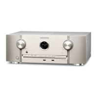
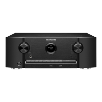
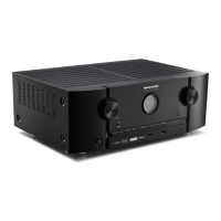
| color | Black / Silver |
|---|---|
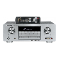
| remote control | RC5400SR |
| system remote function | Pre-Coded |
| maximum dimensions (w x d x h) | 440 x 160 x 463 mm |
| composite in/out | 5/3 |
|---|---|
| s-video in/out | 5/3 |
| component in/out | 2/1 |
| analogue in/out | 8/4 |
| digital optical in/out | 2/1 |
| digital coaxial in/out | 2/1 |
| pre-amplifier out | 6.1 channels |
| multi-channel in | 6.1 channels |
| speaker terminal | Heavy Duty Screw, 6 channels |
| ac outlets | 1 x Unswitched |