13
14
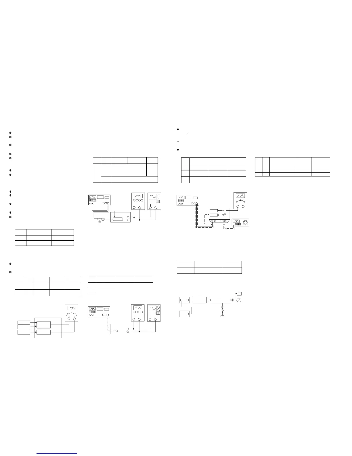
6. ADJUSTMENT PROCEDURE
(1) ALIGNMENT INSTRUCTIONS
EQUIPMENT NEEDEDIMPORTANT
AM Signal Generator1.Check power-source voltage.
FM Signal Generator2.Set the function switch to band
aligned.
Oscilloscope3.Keep the function input as low as possible
to adjust.
VTVM(AC,DC) accurately.
Test loop antenna (MW Adjustnent) 4.Modulation and
modulation frequency.
Dummy antenna(FM Adjustment)
Stereo signal modulator.
Distortion analyzerModulationModulation Frequency.
EQUIPMENT NEEDEDIMPORTANT
AM Signal Generator1.Check power-source voltage.
FM Signal Generator2.Set the function switch to band
aligned.
Oscilloscope3.Keep the function input as low as possible
to adjust.
VTVM(AC,DC) accurately.
Test loop antenna (MW Adjustnent) 4.Modulation and
modulation frequency.
(7) FM/MW TUNED LEVEL ADJUSTMENT
FM Signal Generator : Connect to FM ANT. Jack (FM IN)
through the dummy.
MW Signal Generator : Connect to MW ANT. Coil thriugh
Loop antenna.
MODULATION
MODULATION
FREQUENCY
MW
30% 400Hz
FM
100%(75KHz) 400Hz
(2) TUNING FREQUENCY RANGE ADJUSTMENT
(FM) DC VOLTMETER
CONNECT TO TEST POINT TP1 and GND
(MW) DC VOLTMETER
CONNECT TO TEST POINT TP1 and GND
FM
AM
GND
GND
TP11
DC EVM
UNIT
(3) MW TRACKING ADJUSTMENT
Signal Generator : Connects to the MW Ant.
Coil through the loop antenna.
Adjust for the indication of VTVM of the wave form of
scope to be maximum.
NO STEP
FREQUENCY
ADJUST FOR
ADJUS-
MENT
1 612KHz Max sensitivity L102
2 1503KHz Max sensitivity CT01MW
3 Repeat steps 1 and 2 several times.
AM-SG
AM LOOP antenna
60cm
MHz
OUTPUT
terminal
AC EVM OSCILLOSCOPE
(4) FM-RF ADJUSTMENT
Signal Generator : Connects to FM ANT. JACK (FM IN)
through the dummy.
NO FREQUENCY ADJUST FOR ADJUSTMENT
1 90.10MHz Max sensitivity L1,L2,L3
2 Repeat step 1 several times
FM-SG
UNIT
MHz
OUT
OUTPUT
terminal
FM ANT
75ohm
AC EVM OSCILLOSCOPE
(5) FM MONO DISTORTION ADJUSTMENT
DC VOLTMETER
Connect to TP02 (-),TP03 (+) through the chockcoil
(100 H).
Signal Generator
Connect to FM ANT. Jack (FM IN) through thedummy.
Distortion Meter
Connect to the output.
NO FREQUENCY ADJUST FOR ADJUSTMENT
1 100.10MHz
DC Voltmeter
0V
T101
2 100.10MHz min T.H.D T102
3 Repeat steps 1 and 2 several times
FM-SG
MHz
Choke coil
output
DC EVM
UNIT
Chassis
TP12
TP13
DISTORTION
ANALYSER
OUT
100 H
(6) FM STEREO SEPARATION
PILOT
SIGNAL
ADJUST FOR ADJUSTMENT
ON
Different of R and L
Must be maximum
VR03
FM-SG Dummy UNIT
FM IN OUTPUT
STEREO
OSCILLOSCOPE
VTVM
VR03
OUT
OUT
STEREO
MODULATOR
EXT
BAND STEP SIGNAL GENERATOR ADJUST FOR ADJUSTMENT
FM 1 100.10MHz 30dB TUNED ON VR02
2 100.10MHz 30dB TUNED OFF VR02
MW 1 999KHz 80dB TUNED ON VR01
2 999KHz 80dB TUNED OFF VR01
NO BAND
FREQUENCY
ADJUST
FOR
ADJUST-
MENT
1FM87.50MHz 1.5V L4
2 MW 522KHz 1V L103