Service Manual 1000660 T5 1000661 T10 1000665 PB5 1000666 PB10 Ecoboiler 231109.doc Page 13 of 22
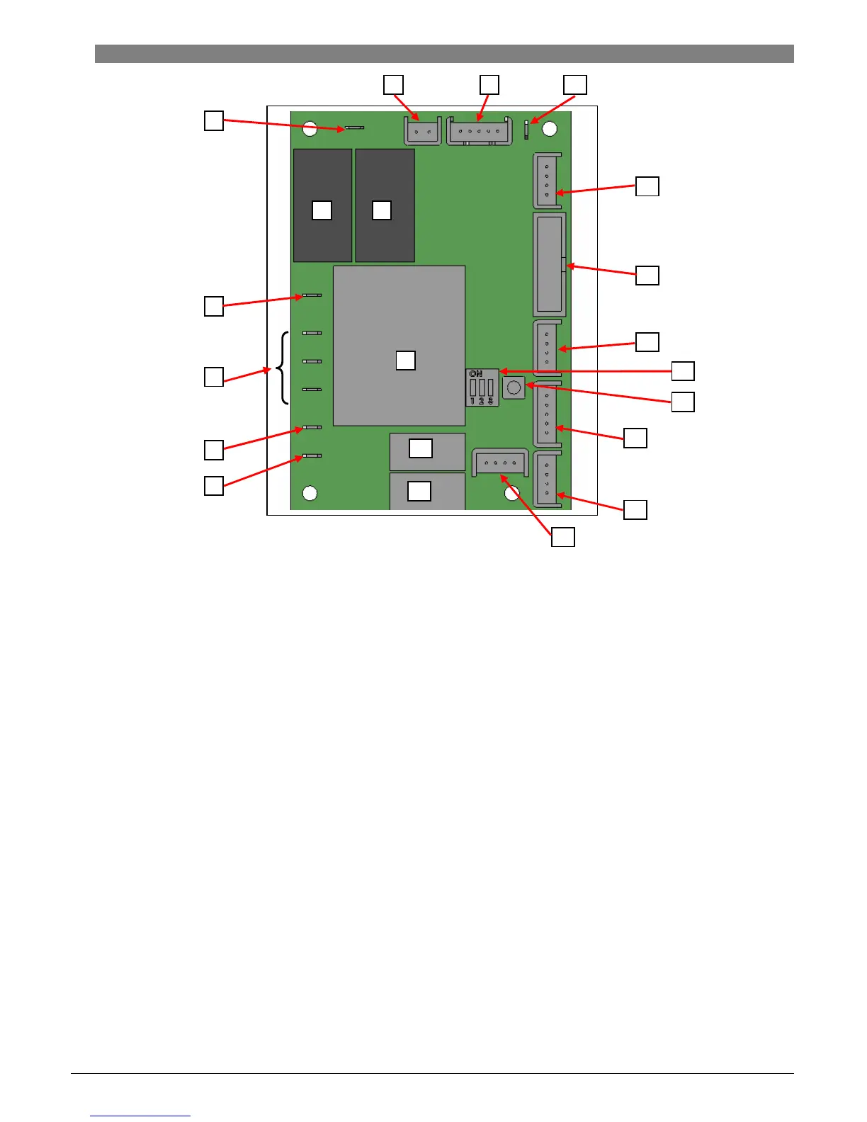
4.5.2. PCB Ecoboiler Control:
COMPONENTS OF PCB ECOBOILER CONTROLLER 2008:
1. Dispense Solenoid Tab
2. Inlet Solenoid Tab
3. Neutral Tabs
4. Transformer
5. Mains Live In Tab
6. Relays - Heater
•
Switch the element
7. Heater Tab
8. On/Off 2-way Connector
•
Short circuited on this Ecoboiler machines – power switch controlled through the display
PCB
9. LED 5-way Connector
10. Earth Tab
11. Daughter PCB Connector (low voltage)
•
Connects to Daughter PCBs – allows switching of more than one element
12. External Connector
13. Thermistor Connector
14. Dip Switch – 3 way
•
Allows selection of software for specific machine
15. Tactile Switch
•
For use during calibration procedure (refer to Calibration in Sec 3.3)
16. Water Level – 5-way connector (low voltage)
•
Connects to Low level and High level probes. Also connects push button on PB variants.
17. Button Connector – 4-way
18. Data I/O Connector – 4-way
19. Relays – Inlet Solenoid
1
2
3
4
5
7
8
9
10
6
6
11
12
13
16
17
14
18
15
19
19