Do you have a question about the Marco MIX Series and is the answer not in the manual?
Steps for installing the MIX boiler unit, covering electrical and plumbing connections.
Guidance on installing the MIX font, including counter cut-out dimensions and hose connections.
Procedure for initial boiler startup, including filling, heating, and ready status indicators.
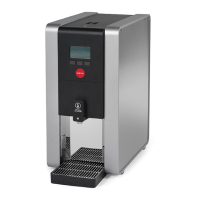
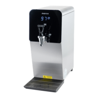
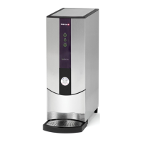
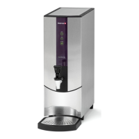
Describes how to operate PB boilers with multiple temperature settings.
Explains the operation of PB boilers configured for single temperature dispensing.
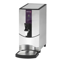
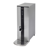
Details the operation of Tap boilers, focusing on dispensing hot water via the tap.
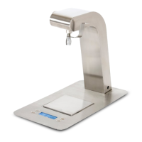
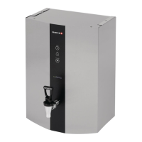
Covers the operation of Under Counter (UC) boilers, including connection and dispensing.
Illustrates the operation of the MIX font for dispensing hot water.
Accessing and adjusting basic user-configurable settings like temperature and volume.
Configuration options for advanced users, including descaling, filter, PIN, and mode settings.
Technical settings for factory assembly or advanced calibration, requiring specialized knowledge.
Step-by-step guide for calibrating dispense volumes and flow rates for optimal performance.
Instructions for safely removing the top lid of the boiler unit.
Procedure for removing side panels to gain access to internal components.
Steps to safely drain the water from the boiler tank, essential before maintenance.
Guide for replacing the Printed Circuit Board (PCB) unit in the boiler.
Instructions for replacing the dispense solenoid or pump assembly.
Procedure for removing the dispense tap from tap version boilers.
Steps for removing the tank lid sub-assembly, including element and probes.
Instructions for removing the heating element from the boiler tank.
Guidance on cleaning and replacing thermistor and level probes.
Procedure for replacing the Triac component within the boiler.
Steps for replacing the inlet solenoid responsible for water filling.
Details on replacing the power supply for the pump in UC version units.
Procedure for descaling the boiler tank to remove mineral buildup.
Instructions for replacing the water filter in the machine.
A guide to identify and resolve common issues based on reported problems and component checks.
Electrical wiring diagram for the PB version boilers.
Electrical wiring diagram for the Tap version boilers.
Electrical wiring diagram for the UC version boilers.
Specific wiring harness diagram for Mix UC3 and UC8 models.
Exploded diagram and parts list for the MIX PB3 model.
Exploded diagram and parts list for the MIX T8 model.
Exploded diagram and parts list for the MIX PB8 model.
Exploded diagram and parts list for the MIX UC3 model.
Exploded diagram and parts list for the MIX UC8 model.
Exploded diagram and parts list for the 3-button MIX font.
Exploded diagram and parts list for the 1-button MIX font.