. 2..4 CAPACITANCE MEASUREMFNTS
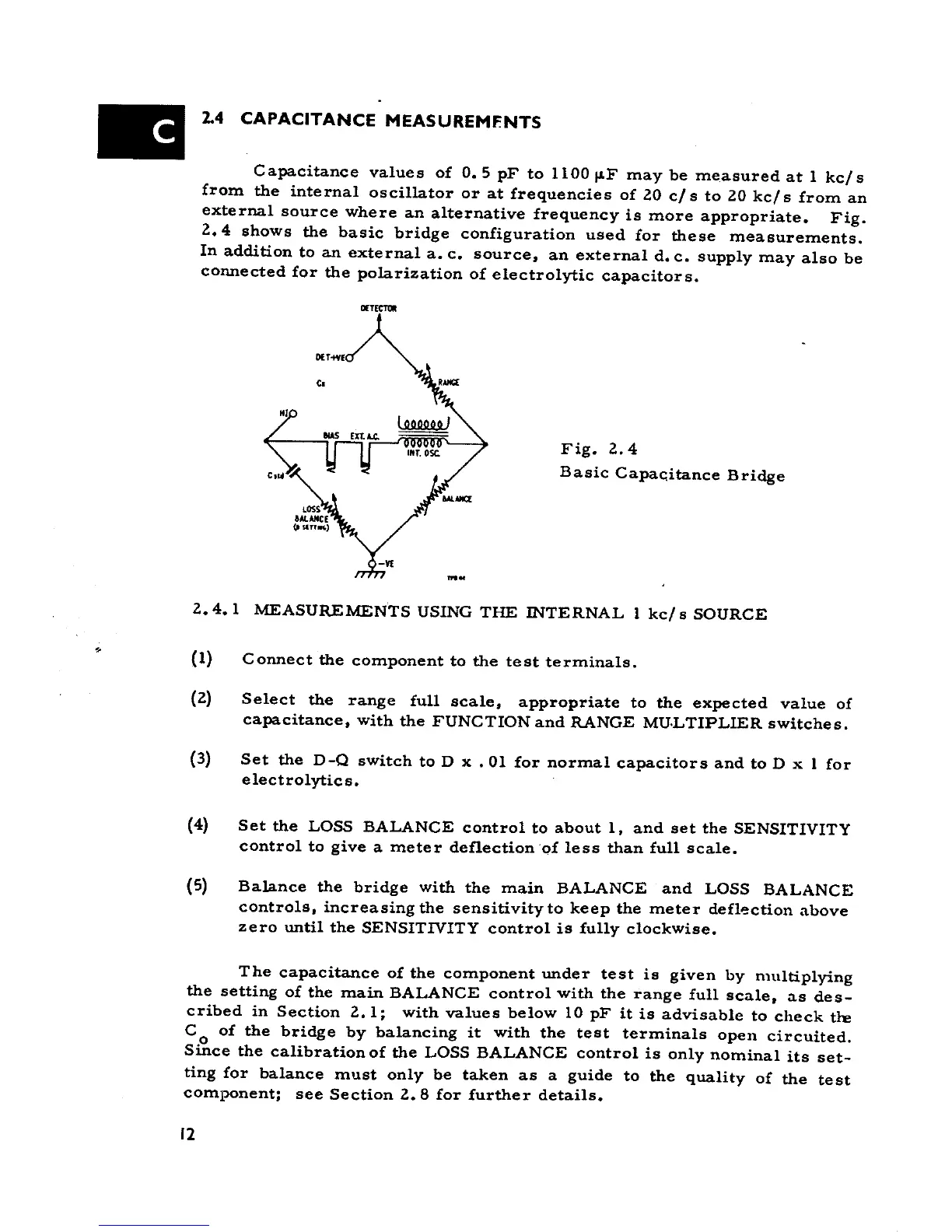
Capacitance values of 0.5 pF to 1100 IIF may be measured at I kcl s
from the internai oscilla.tor or at frequencies of 20 cl s to 20 kcl s from an
external source where an alternative frequency is more appropriate. Fig.
2.4 shows the basic bridge configuration used far these measurements.
In addition to an external a. c. source, an external d. c. supply may alBo be
connected far the pola.rization of electrolytic capacitors.
MTECTW
c.
Fig. 2.4
Basic Capac;itance Bridge
'"~
2.4. l MEASUREMENTS USING THE INTERNAL l kc/ s SOURCE
.. (I) Connect the component to the test terminale.
(2) Select the range full scale, appropriate to the expected value of
capacitance, with the FUNCTION and RANGE MU.LTIPLIER switches.
(3) Set the D-Q switch to D x .01 far normal capacitors and to D x l far
electrolytics.
(4) Set the LOSS BALANCE contrai to about l, and set the SENSITIVITY
contrai to give a meter deflection of lese than full scale.
(5) Bala.nce the bridge with the main BALANCE and LOSS BALANCE
controls, increasing the sensitivity to keep the meter defl~ction above
zero until the SENSITIVITY contrai is fully clockwise.
The capacitance of the component under test is given by rnltltiplying
the setting of the main BALANCE contrai with the range full scale, as des-
cribed in Section 2.1; with values below lO pF it is advisable to check tre
C of the bridge by bala.ncing it with the test terminale open circuited.
o
Since the calibration of the LOSS BALANCE contrai is only nominai its set-
ting far balance must only be taken as a guide to the quality of the test
component; see Section 2.8 far further details.
12