2.4.2 MEASURE:MENTS USING AN EXTERNAL A. F. SOURCE
An alternative frequency may sometimes be used to advantage far -.
high value capacitors, especially electrolytics as these are often manufac-
tured to have a specific 50 to 120 c/s value. Aiso at 10wer frequencies the
effect of lead inductance is much lesa significant, and the LOSS BALANCE
contrai setting becomes proportionately less criticaI.
The measurement procedure is similar to that described in Section
2.4.1 and details of connections are given in Section 2.7. When using
frequencies other than l kc/ s multiply the D and Q scales bya factor OI
f/1000, where f is the frequency in CIBo
2.4.3 ELECTROLYTIC CAPACITORS AND USE OF POLARIZING BIAS
Due to their construction electrolytic capacitors often have relatively
large series and paral1elloss components. The series 10ss is usually
greater and so the D setting of the LOSS BALANCE controls should be used,
this being essential when a polarizing voltage is applied.
The LOSS BALANCE adjustment may be found to be rather criticaI
therefore the sensitivity should be reduced in arder to obtain a more
satisfactory balance. Too high an accuracy has 1ittle meaning far very
high loss components and no more sensitivity is desirable than is justified
by the component quality.
Application of Polarizing D. C. Bias
-
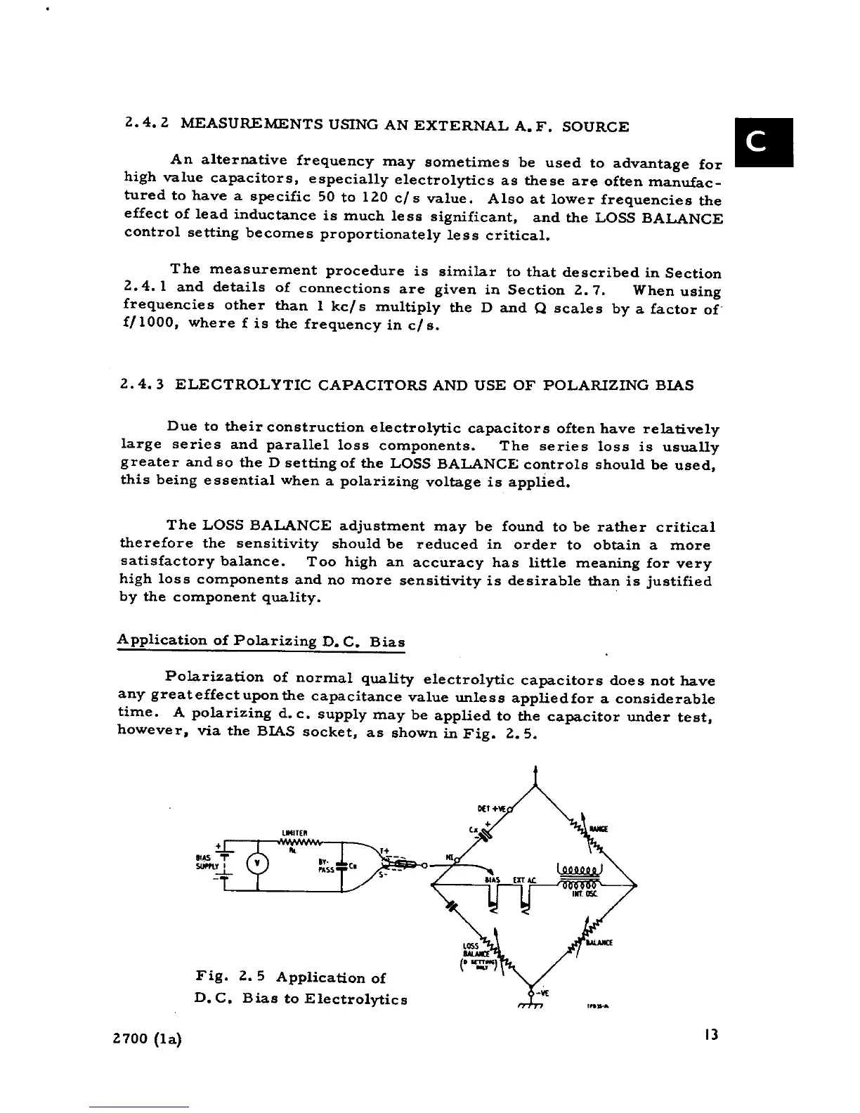
Polarization of normal quality e1ectrolytic capacitors does not have
any greateffectuponthe capacitance value unless appliedfor a considerable
time. A polarizing d. c. supply may be applied to the capacitor under test,
however, via the BIAS socket, as shown in Fig. 2.5.
"',TE"
~~~~~==~E::~~-o" T +
..~ or y ". --,
""'" , PASS C. --
.:-'- s-
Fig. 2. 5 Application of
D. C. Bias to Electrolytics , 2700 (la) 13