is passed through the component to take the operating point to the desired
position on the B/H curve.
Measurements of this type may be carried out with this bridge using
several alternative methods~-
lA
v*
soov
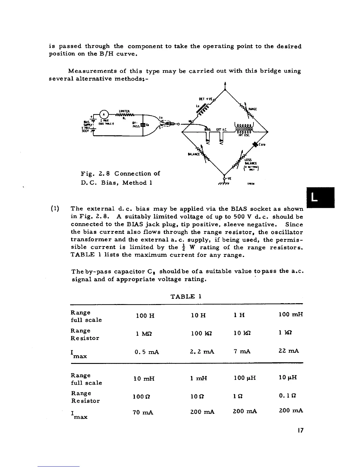
Fig. Z.8 Connection of
D. C. Bias, Method l '"IO
(l) The external d. c. bias may be applied via the BIAS socket as shown .
in Fig. Z.8. A suitably limited voltage of up to 500 V d. c. should be
connected to the BIAS jack plug, tip positive, sleeve negative. Since
the bias current alBo flows through the range resistor, the oscillator
transformer and the external a. c. supply, if being used, the permis-
sible current is limited by the t W rating of the range resistors.
TABLE l lists the maximum current far any range.
Theby-pass capacitor CI shouldbe ora suitable value topass the a.c.
signal and of appropriate voltage rating. .
TABLE l
Range 100 H lO H l H 100 mH
full scale
Range l M} 100 141 lO 141 l 141
Re sistor
I 0.5 mA Z. Z mA 7 mA ZZ mA
max
Range lO mH l mH 100 ~H lO ~H
full scale
Range 100(1 10(1 l a 0.1 a
Re sistor
I 70 mA ZOO mA ZOO mA ZOO mA
max
17