Excessive capacitance between the bias supply and the bridge case
should be avoided, aS it may affect the LOSS BALANCE setting.
Isolation of one or the other from true earth is advisable.
CAUTION: To avoid high transient voltages short circuit Lx before
switching off the bias supply.
lIMIT" "
lOtO ...
-~CJ
IIMX ~J20'"
40... - 5OOY
.
IIA' .
"-Y I
-~
. m"
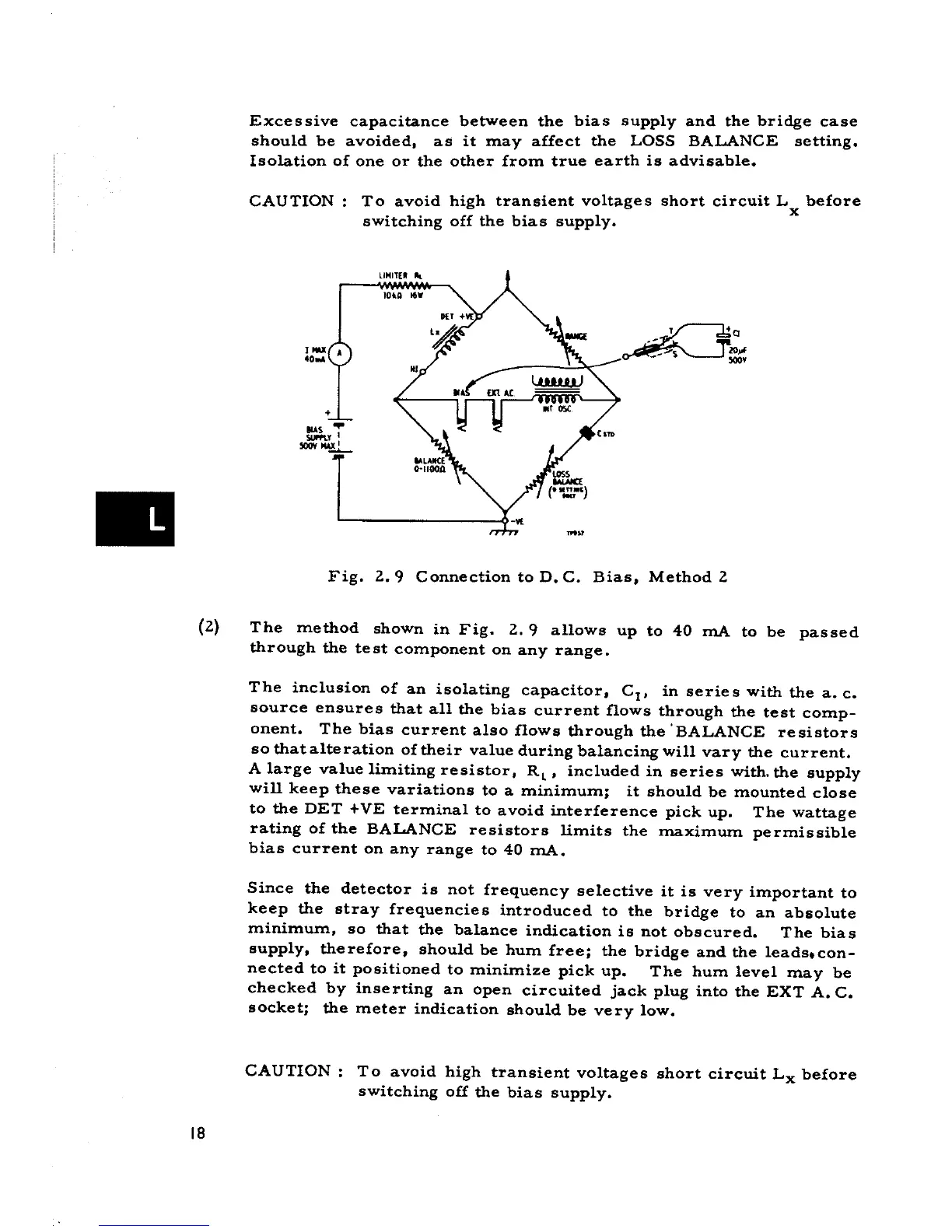
Fig. 2.9 Connection to D. C. Bias, Method 2
(2) The method shown in Fig. 2. 9 allows up to 40 mA to be passed
through the test component on any range.
The inclusion of an isolating capacitor, CI, in series with the a. c.
source ensures that alI the bias current flows through the test comp-
onent. The bias current also flows through the 'BALANCE resistors
so thatalteration oftheir value during balancing will vary the current.
A large value limiting resistor, RL' included in series with. the supply
will keep these variations to a minimum; it should be mounted close
to the DET +VE terminaI to avoid interference pick up. The wattage
rating of the BALANCE resistors limits the maximum permissible
bias current on any range to 40 mA.
Since the detector is not frequency selective it is very important to
keep the stray frequencies introduced to the bridge to an absolute
minimum, so that the balance indication is not obscured. The bias
supply, therefore, should be hum free; the bridge and the leadstcon-
nected to it positioned to minimize pick up. The hum leve l may be
checked by inserting an open circuited jack plug into the EXT A. C.
socket; the meter indication should be very low.
CAUTION: To avoid high transient voltages short circuit Lx before
switching off the bias supply.
18