..
.
,. .
... .,.. 'AS'"
"-',
S«N ~
O$.~=3- ". ~ ti
- ,. ...,
- ..,.
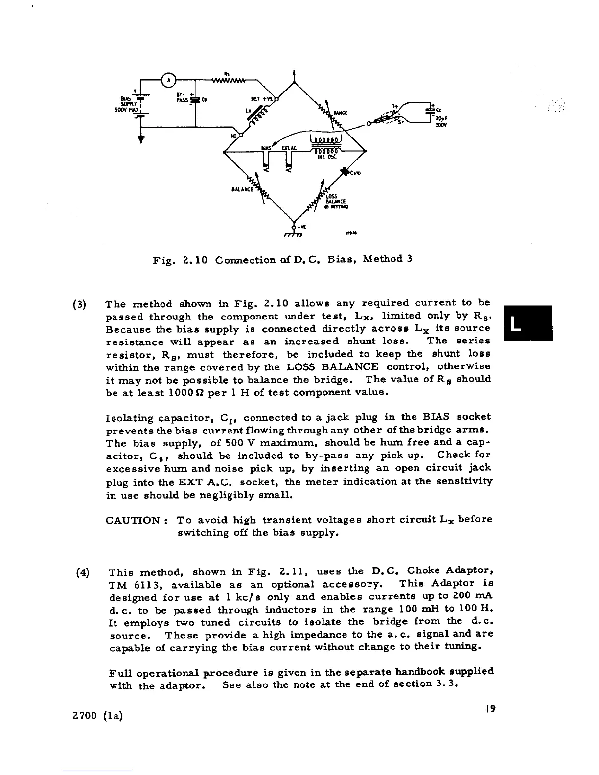
Fig. 2.10 Coxmection a£ D. C. Bias, Method 3
(3) The method shown in Fig. 2.10 allows any required current to be
passed through the component under test, Lx, limited only by Rs'
.Because the bias supply is coxmected directly across Lx its source
resistance will appear as an increased shunt loss. The series
resistor, Rs. must therefore, be included to keep the shunt loss
within the range covered by the LOSS BALANCE control, otherwise
it may not be possible to balance the bridge. The value of Rs should
be at least 1000fl per l H of test component value.
Isolating capacitor, CI, connected to a jack plug in the BIAS socket
prevents the bias current flowing through any other of the bridge arms.
The bias supply, o£ 500 V maximum, should be hwn free and a cap-
acitor, C.' should be included to by-pass any pick up. Check £or
excessive hwn and noise pick up, by inserting an open circuit jack
plug into the EXT A.C. socket, the meter indication at the sensitivity
in use should be negligibly small.
CAUTION: To avoid high transient voltages short circuit Lx before
switching off the bias supply.
(4) This method, showninFig. 2.11, uses the D.C. ChokeAdaptor,
TM 6113, available as an optional accessory. This Adaptor is
designed for use at l kc/ s only and enables currents up to 200 mA
d. c. to be passed through inductors in the range 100 mH to 100 H.
It employs two tuned circuits to isolate the bridge from the d.c.
source. These provide a high impedance to the a. c. signal and are
capable of carrying the bias current without change to their tuning.
Full operational procedure is given in the separate handbook supplied
with the adaptor. See alBo the note at the end of section 3.3.
2700 (la) 19