(l) Connectthe component to the testterminals and check the mechanical
zero of the meter with the bridge switched OFF.
(2) Select the range fun scale, appropriate to the expected value of resis-
tance, with the RANGE MULTIPLIER switch. Set the FUNCTION switch
to R INT D. C.
(3) Set the SENSITIVITY control to give a meter deflection of less than
fun scale. Ifthe deflectionis left of zero the value of the unknown is
higher than the setting of the bridge and vice versa.
(4) Balance the bridge with the main BALANCE control, increasing the
sensitivity as necessary to give a fina l balance with the meter at zero
and the SENSITIVITY control fully clockwise.
The resistance value of the component under test is given by multiply-
ing the setting of the BALANCE control with the range fun scale, as des-
cribed in Section 2. l.
2.6.4 MEASUREMENTS USING AN EXTERNAL D. C. SOURCE
By using an external d. c. source of higher voltage than the 9 V inter-
naI battery greater discrimination may be obtained on ranges of lO ~ fun
scale and above. No advantage will be gained, however, by using ari exter-
nal d.c. source on the lower ranges, except for very low values as described
later.
High Resistance
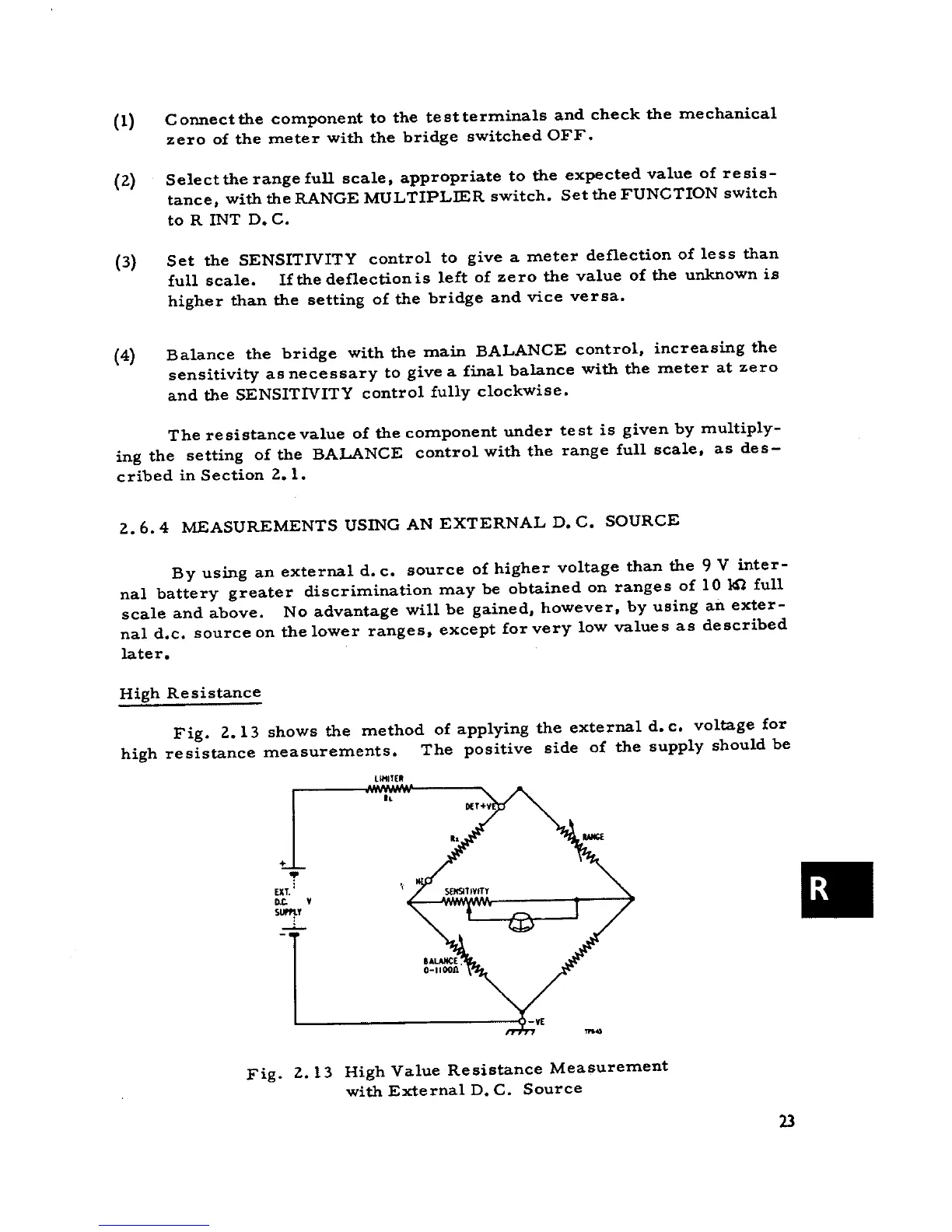
Fig. 2.13 shows the method of applying the external d. c. voltage for
high resistance measurements. The positive side of the supply should be
,..,TE'
°,
+
EXT.T ,.
.~ .
s~
-..
Fig. 2.13 High Value Resistance Measurement
with External D. C. Source
23