[.'
connected to the DET +VE terminaI and the negative to the -VE (chassi~
terminaI. Limiting resistor RL must be included to protect the bridge
resistors from excessive currents. Tabie 3 gives the minimum value of
limiting resistor and maximum permissible value of voltage for any range.
TABLE 3
Range lO Kl 100 Kl l M1 lO M1
V 22 V 70 V 220 V 500 V
max
RL. 3600 2.2Kl 25Kl 50Kl
mm
Measurement procedure is similar to that described in Section 2.6.3. I
Care should be taken when using high voltages; always switch off the externa
supply before altering the position of the FUNCTION switch.
Low Resistance
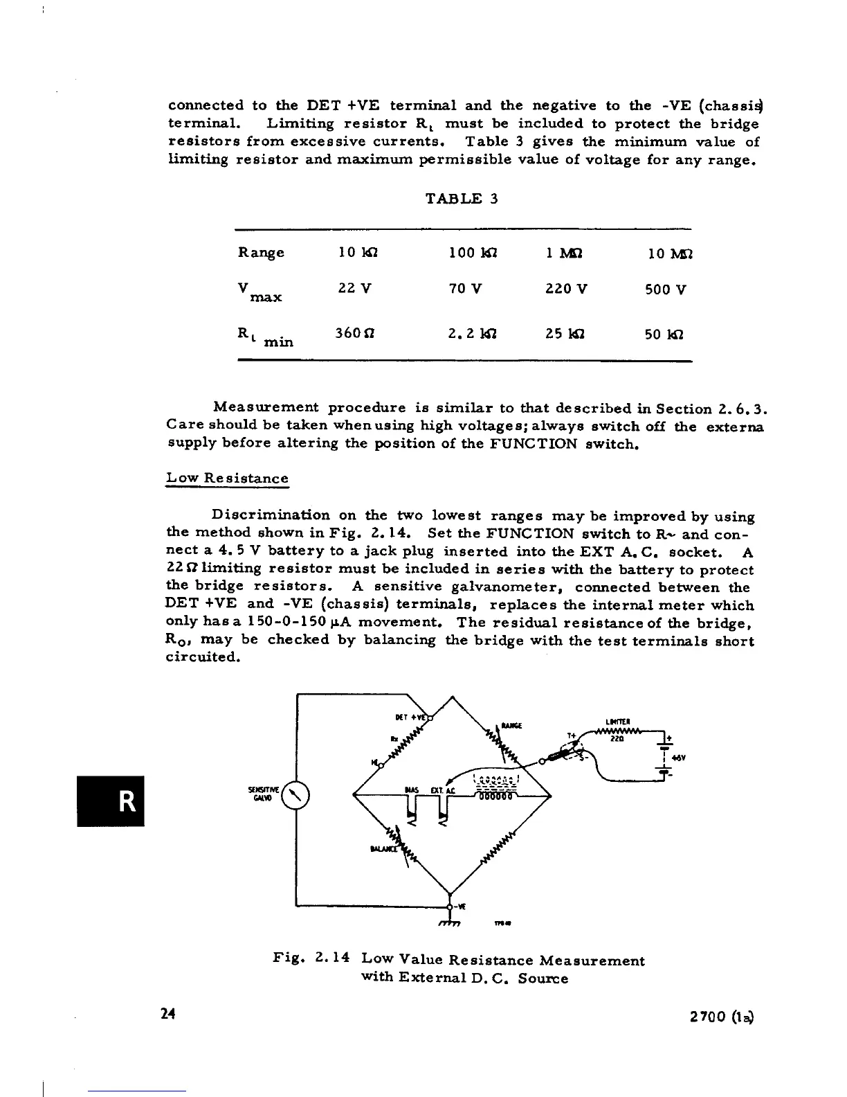
Discrimination on the two lowest ranges may be improved by using
the method shown in Fig. 2.14. Set the FUNCTION switch to R- and con-
nect a 4.5 V battery to a jack plug inserted into the EXT A. C. socket. A
22alimiting resistor must be included in series with the battery to protect
the bridge resistors. A sensitive galvanometer, connected between the
DET +VE and -VE (chassis) terminals, replaces the internaI meter which
only has a 150-0-150 /lA movement. The residual resistance of the bridge,
Ro, may be checked by balancing the bridge with the test terminals short
circuited.
L_I
O"'~~~:~:::~J+ 'lO +
. -
I
-- - I 46-
-'-
. ~N( "
'"-
Fig. 2.14 Low Value Resistance Measurement
with External D. C. So=e
M 2700 (1,.}