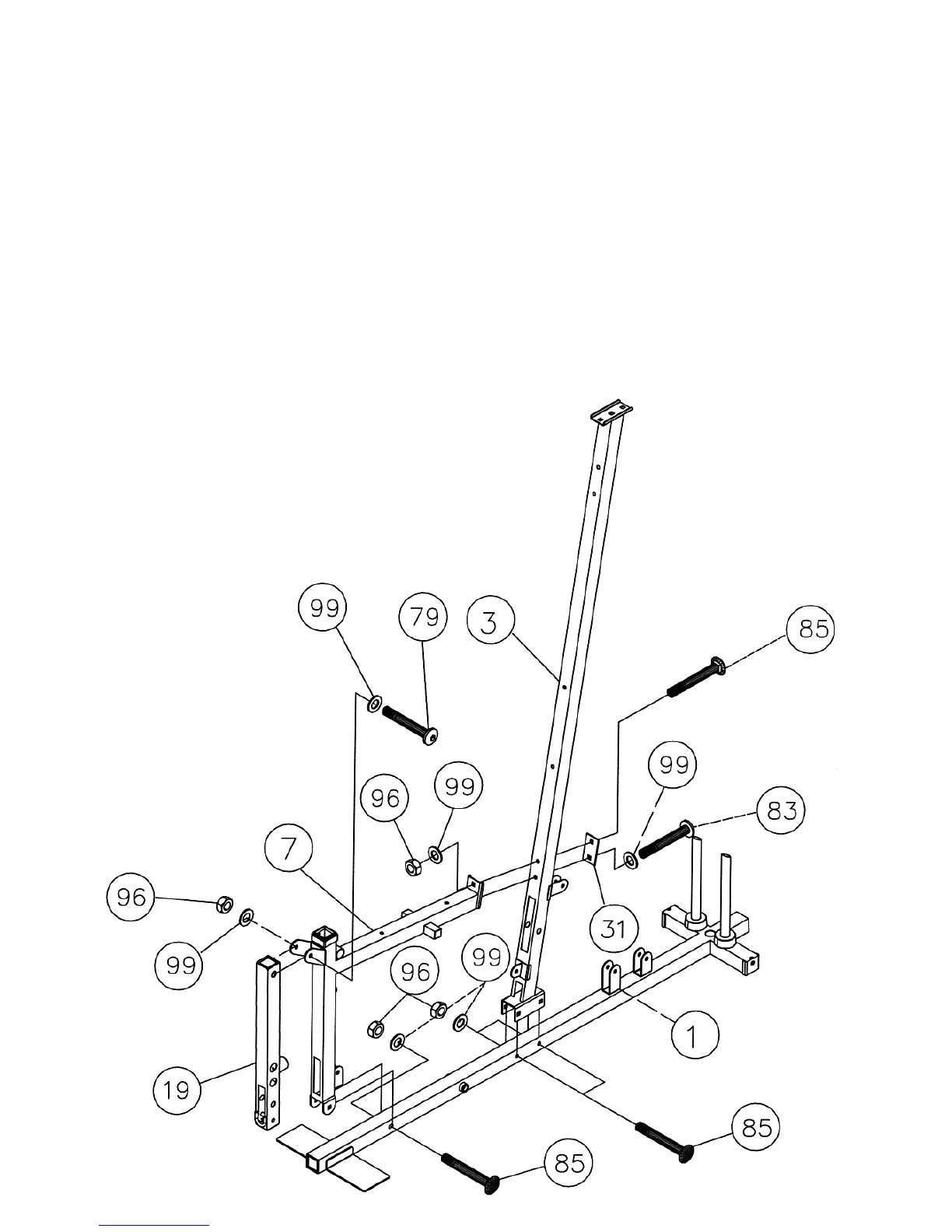
STEP 3 (See Diagram 3)
A.) Attach the Right Vertical Beam (#3) to the Right Base Frame (#1). Secure it with two
M10 x 2 ½” Carriage Bolts (#85), ∅¾” Washers (#99), and M10 Aircraft Nuts (#96). DO
not tighten the Nuts and Bolts yet.
B.) Attach the Right Seat Support (#7) to the Right Vertical Beam (#3). Secure it with one
M10 x 2 ½” Carriage Bolt (#85), one M10 x 2 3/8” Allen Bolt (#83), one 3 1/8” x 1 ¾”
Bracket (#31), two Ø ¾” Washers (#99), and one M10 Aircraft Nut (#96).
C.) Attach the Right Seat Support (#7) to the Right Base Frame (#1). Secure it with one
M10 x 2 ½” Carriage Bolt (#85), ∅ ¾” Washer (#99), and M10 Aircraft Nut (#96).
D.) Attach the Leg Developer (#19) to the bracket on the Right Seat Support (#7). Secure it
with one M10 x 2 7/8” Allen Bolt (#79), two Ø ¾” Washers (#99), and one M10 Aircraft
Nut (#96). Do not over tighten the Leg Developer, make sure it is able to swivel.
DIAGRAM 3


 To Next Page