User’s Guide
5
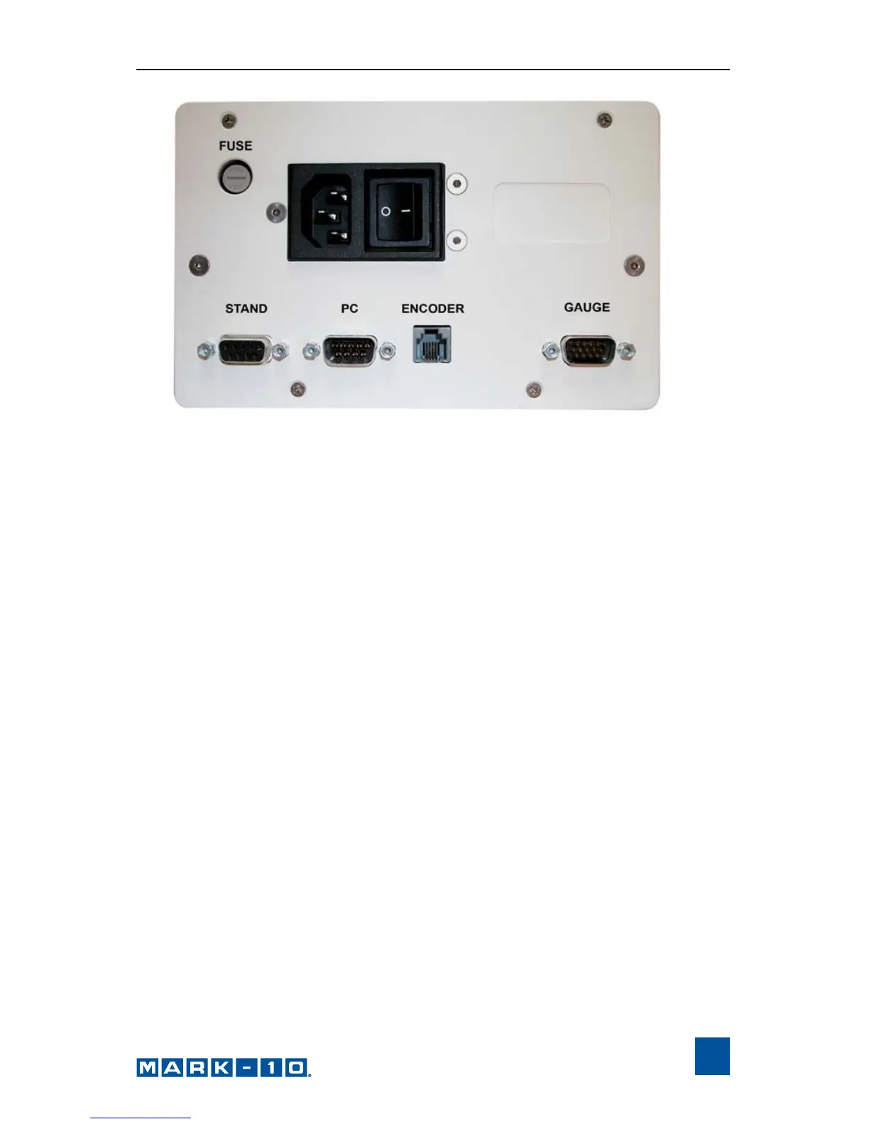
1. Fuse
2. STAND / Controller Cable Connector
Plug one end of the cable into this connector, and the other end into the
connector adjacent to the motor on the test stand. If this cable is not
connected, the error message ENCODER ERROR will be shown on the
display and the test stand cannot be operated.
3. PC / PC Control Connector
Plug one end of the 09-1056 serial cable into this connector, and the other
end into a serial connector on a computer.
4. Power Plug Receptacle
Plug the power cord in here.
5. ENCODER / Travel Indication Connector
Applicable for TSTM / TSTMH test stands only
Plug one end of the RJ11 cable into this connector, and the other end into
the connector on the underside of the mechanism housing on the test stand.
6. GAUGE / Gauge Cable Connector
Plug one end of the 09-1143 cable into this connector, and the other end
into a Series 5, Series BG or BGI gauge.