18
7. trigger in and out connectors
Provide DC trigger control. One 1/8-inch mini-jack labeled
trigger in is available to receive 12 or 5V DC signals from a
connected component, and one 1/8-inch mini-jack labeled
trigger out is available to pass these signals along to a connected
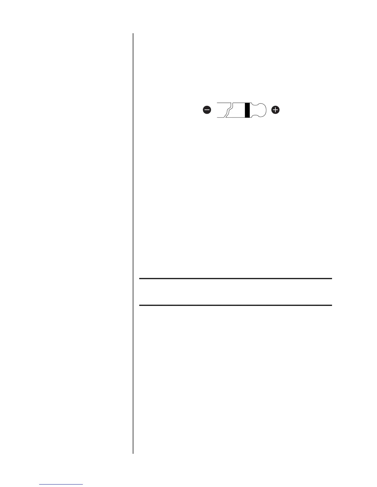
power amplifier. The illustration below shows tip polarity
requirements.
Connect the trigger in connector on the Nº432/431 to the
trigger out connector on a compatible component. Toggling
the connected component between on and standby will toggle
the Nº432/431 between on and standby or on and sleep
mode (depending on the power save mode switch setting).
Connect the trigger out connector on the Nº432/431 to the
trigger in connector on a compatible power amplifier. The
Nº432/431 will pass DC signals along to the connected power
amplifier, creating a “daisy-chain” of trigger control.
8. power save mode switch
Determines the Nº432/431’s response to reductions in DC trigger
voltage, from “high” (5-12V) to “low” (0V).
Important! DO NOT change the power save mode switch setting when the
Nº432/431 is powered on. Make sure power is disconnected
from the ~ac mains connector before making adjustments.
When the power save mode switch is set to on, the
Nº432/431 powers on in sleep mode. If the Nº432/431 is
configured for trigger control, incoming DC signals toggle the
Nº432/431 between on and sleep mode.
When the power save mode switch is set to off, the
Nº432/431 powers on in standby. If the Nº432/431 is
configured for trigger control, incoming DC signals toggle the
Nº432/431 between on and standby.