3
INSTALLATION
Service Connections
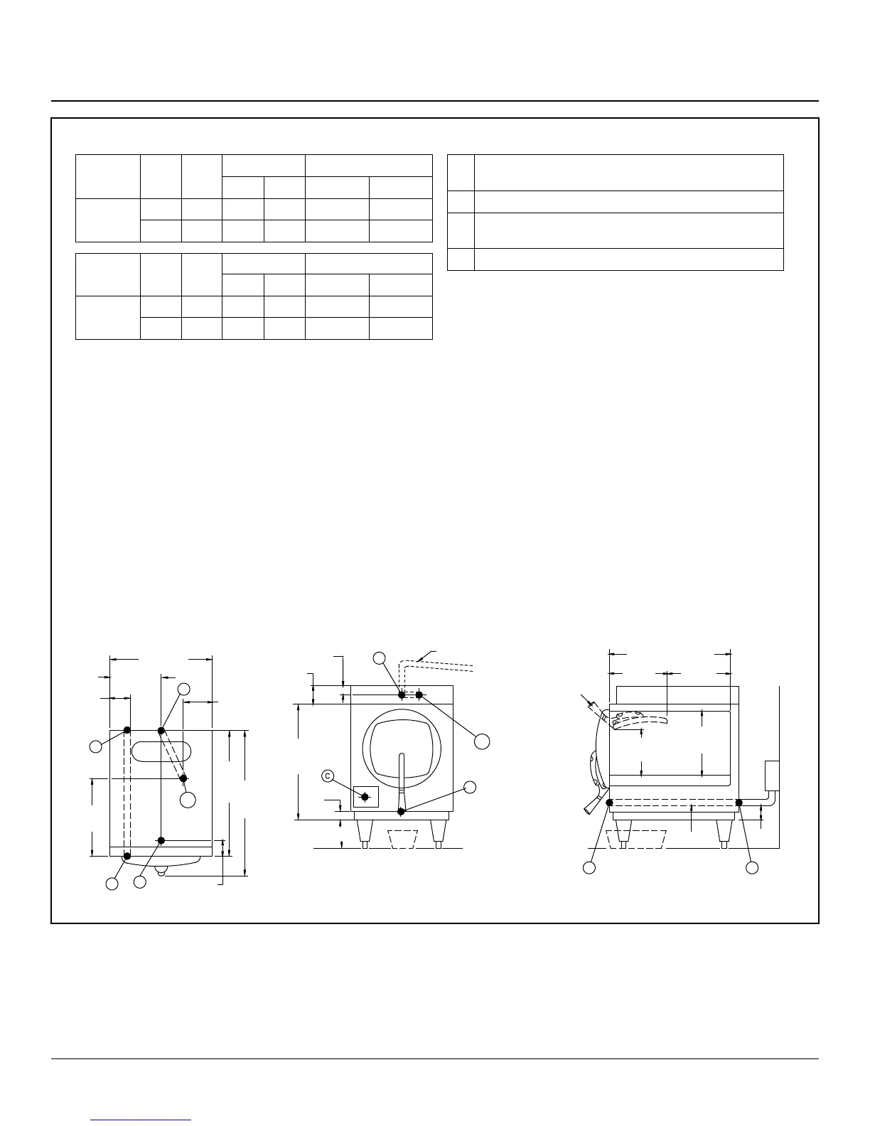
Figure 1
ELECTRICAL SPECIFICATIONS
Domestic
Models
kW Hz
1 Phase
3 Phase
208V 240V 208V 240V
STM-E
STM-EL
9.3 60 45A - 26A -
12.4 60 - 52A - 30A
Export
Models
kW Hz
1 Phase
3 Phase
220V 240V 220/380V 240/415V
STM-EX
STM-ELX
10.4 50 48A - 16A -
12.4 50 - 52A - 18A
Unit must be grounded. Main supply voltage fluctuations are not to
exceel ± 10% nominal supply voltage.
WATER SUPPLY
Good quality water feed is the responsibility of the owner. Water qual-
ity must be within the following general guidelines.
TDS: 40-125 ppm Hardness: 35-100 ppm Chlorine: <0.2 ppm
Silica: <13 ppm Chlorides: <25 ppm
Chloramine: <0.2 ppm pH: 7.0 - 8.5
The best defense against poor water quality is a water treatment
system designed to meet your water quality conditions.
Appliance to be installed with backflow protection according to fed-
eral, state or local codes.
DIMENSIONS ARE IN INCHES [MM]
SEE NOTE 2
B
2 [57]
4.63 [117]
23 [584]
1 [25]
6 [152]
B1
A
4 [102]
ADJ. LEGS
Customer provided Drain Catch Pan
Approx. 4-6 quarts (3.8-5.7 liters)
21 [533] CHAMBER
9 [230]
12 [305]
DOOR IN
OPEN POSITION
9 [228]
CLEARANCE
11 [280]
CLEARANCE
C
D
CONDUIT
3 [76]
Locate electric box as close to
sterilizer as possible and per
local electrical codes
D
CONDUIT
15.5
[394]
3.5
[89]
C
A
9.34 [237]
18.69 [475]
B
SEE
NOTE 2
4.75
[121]
B1
25 [635]
1.5 [38]
30 [762]
SERVICE CONNECTIONS
A Drain - 1/2” (13mm) N.P.T. of 3/8” (10mm) OD copper
(see note 1)
B Steam Exhaust Connection - 5/8” (16mm) (see note 2)
C Electrical Connection - (*see electrical specifications
table)
D Power Supply
NOTES:
1. An air break must be provided if a unit drain line is run.
2. Vent exhaust to atmosphere. B1 is actual connection, but
must exit casing at B.
3. Heat of Rejection (Heat Loss Into the Room) 6,000
BTU’S.
IMPORTANT: Exhaust line must be vented to the outside to elimi-
nate the exhaust steam and the accompanying noise from enter-
ing the room. Use 1/2” (13mm) copper tubing or suitable alternate.
The overall height and length of the line should not rise more then
4’ (1.2 meters) above the unit and exceed 15’ (4.5 meters) with a
minimum of bends. The line should slope downward after leaving
the sterilizer in order to ensure condensate drainage.
IMPORTANT: Failure to comply with this outline will affect the
sterilization process.
When an exhaust condenser is supplied; the following services
must be provided: 1/2” (13mm) cold water: 1” (25mm) waste:
115V electrical line.