15
1 2 3 4 5 6 7 8 9 10
ON
AC/DC
12-18V
Fahrgleis
Halteab-
schnitt
Halteab
-
1
2
3
4
1
2 3
4
5 6
7
8
T
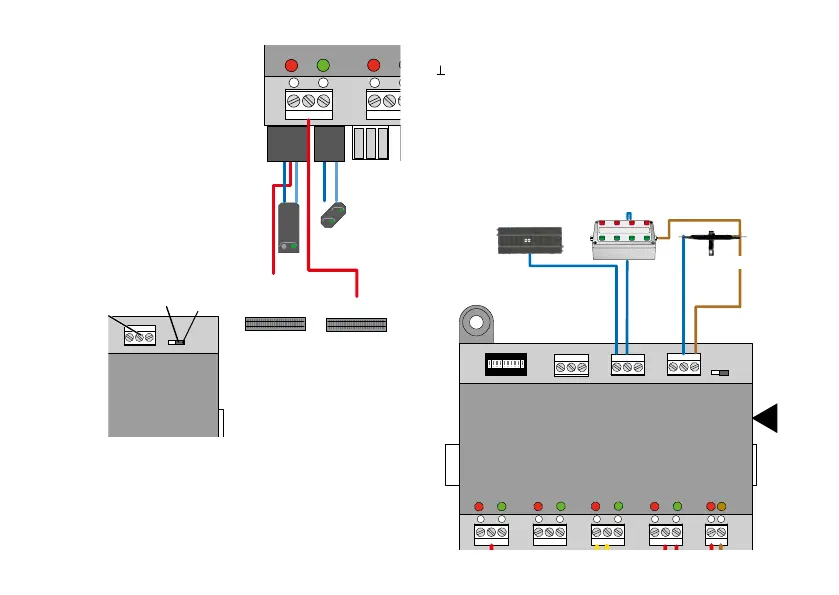
Anschluss für 66360+60822
Fahrgleis
Connections for the Hobby Signal
Stopping
Area
Track
The nearby diagram shows the
connections for the signal block
and the regular track.
Connections for External Contact Generators
Inputs 1 - 8 are for switching the outputs on the M 84. Circuit
tracks, reed switches, or control boxes can be connected
directly to these inputs. A requirement is that the contact
generators must be connected with the brown wire (0) for
the locomotive operating current.
1 2 3 4 5 6 7 8 9 10
ON
1
2
3
4
1
2 3
4
5 6
7
8
T
Anschluss für 66360+60822
B 0
0
Assignment of the switching inputs:
Common wire to all contact generators.
The circuit track requires a special (0) connection; it is
connected in the track layout.
Inputs 1 - 8 switch users / color light signals 1 - 4.
User 1 = is switched by 1 red and 2 green
User 2 = is switched by 3 red and 4 green
User 3 = is switched by 5 red and 6 green
User 4 = is switched by 7 red and 8 green
If no Hobby signals are con-
nected, we recommend turning
the switch off (8) to reduce the
current consumption.
1 2 3 4 5 6 7 8 9 10
ON
1
2 3
4
5 6
7
8
T
8
ein
7
Connection for 66360/66365 + 60822