9
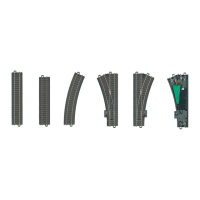
At least one section of 20188 track should be installed before
and after the uncoupler track in order to ensure reliable
uncoupling.
72752
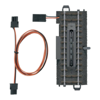
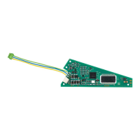
6. Connections for and Operation of the
Uncoupler Track
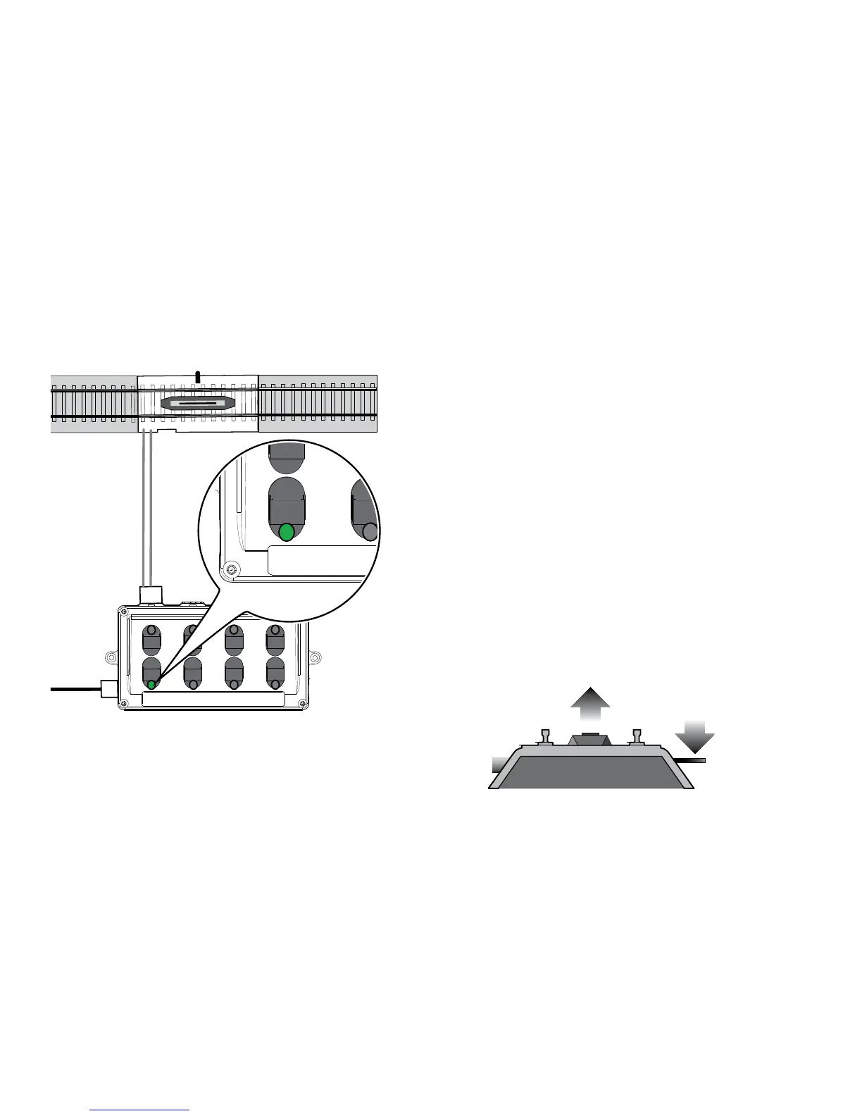
Plugthe3-pinplugontheuncouplertrack(20997)intothe
3-pin socket on the back of the 72752 control box. Then the
green LED for the connection in use lights up.
The uncoupler track can be operated with the upper button.
The green LED goes out while the uncoupler track is being
activated.
The LED is only activated at those buttons that are con-
nected to a turnout or uncoupler track.
Note: This uncoupler track is designed for momentary
activation. The built-in protective circuit prevents overloads
in the event of accidental continuous contact. When this
happens, the uncoupler is ready for operation again after a
short interruption.
This uncoupler track can also be operated manually with the
hand lever.
Hand lever