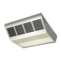
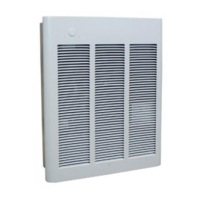
Installation of Recess Mounted Heaters in T-Bar
Ceiling (See Figures 3 and 4)
The recess mounted heater will mount in any standard 2’ x 2’
(609 mm x 609 mm) T-Bar (drop) ceiling. See Warning No. 4 for
minimum mounting clearance and Warning No. 9, page 1.
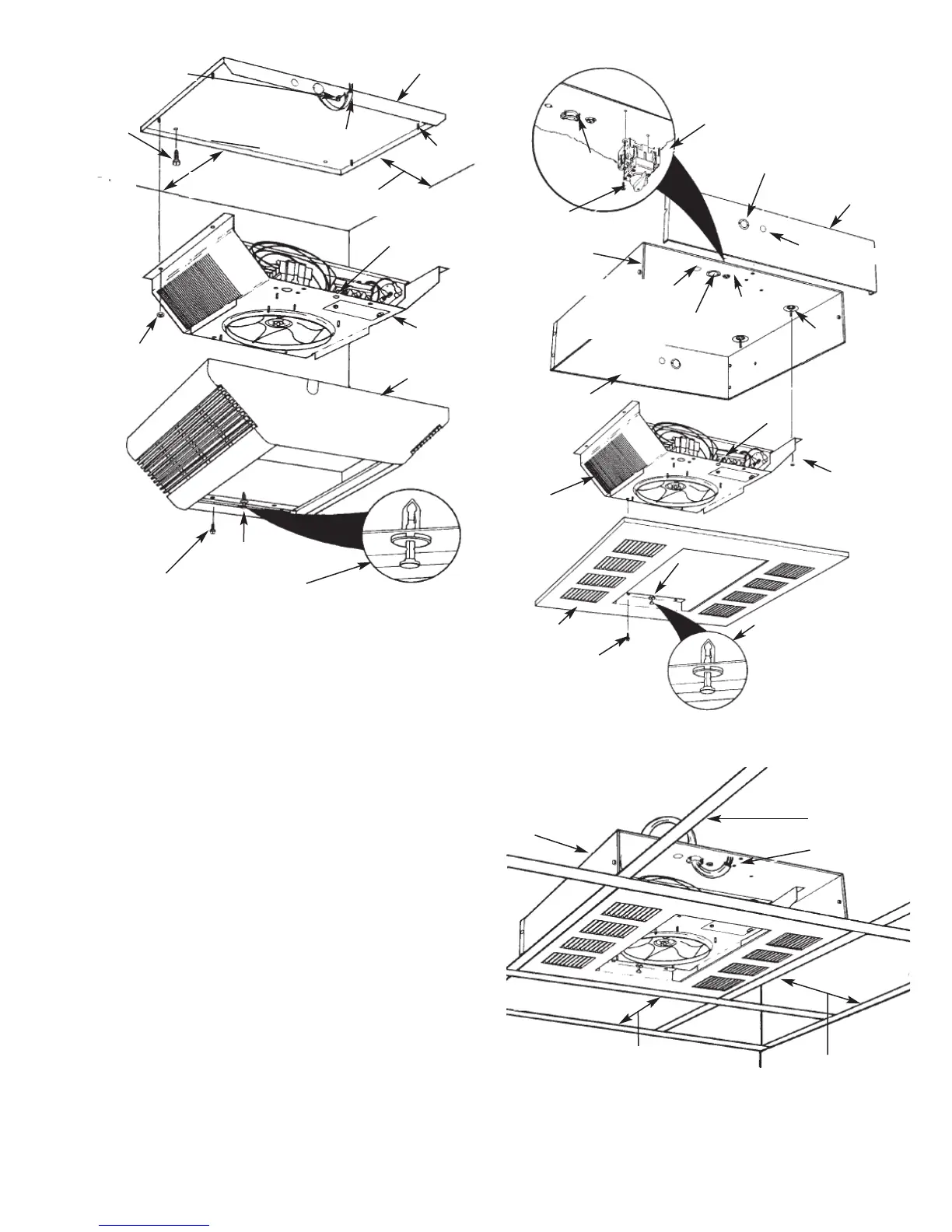
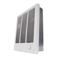
1. Remove Recess Mounted Heater assembly from carton.
Heater assembly includes (1) recess mounting box, (1)
heater, (1) recess mount face plate and (1) set of discharge
grilles, Figure 3.
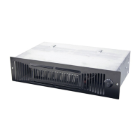
2. Remove recess mount box from assembly. Remove four (4)
nuts from studs so heater can be removed from recess
mounting box. Do not discard nuts since these will be used
in Step 9 to mount heater section back on to the recess
mounting box.
3. Remove three screws and the side of the recess mounting
box to allow for easier wiring (Figure 3).
4. Remove one of the knockouts and install a cable or conduit
connector (Figure 3).
5. Install the optional disconnect switch CDFDS (if required as
shown in Figure 3). Refer to accessory instal lation manual
for proper wiring.
6. Install optional controls (if required) into the heater section in
accordance with the Instruction Sheet packaged with the
control.
7. To wire the heater, thermostat, reduce wattage or convert
from single to three-phase voltage, refer to “Field Conversion
for Lower Wattage Rating” or “Conversion for 3ø Installation”
on page 7 and wiring diagrams, Figure 13, page 7.
3
Nut (4)
Screws
or Bolts
(Not Supplied)
Screw (4)
Thumb Pin Hole
(2)
Insure that “Thumb Pin” is pulled out before positioning
the surface mounting enclosure on the heater section.
Depress “Thumb Pin” after surface enclosure is sealed
firmly against the heater section.
Grounding Screw
Surface Mounting
Plate
Stud (4)
Power Supply
Cable
Thumb Pin
Hole (2)
Heater Section
Surface Mounting Enclosure
12” (305 mm) Min. 4 kW
24” (609 mm) Min. 5 kW
FFiigguurree 22
1
2” (305 mm) Min. 4 kW
2
4” (609 mm) Min. 5 kW
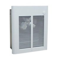
FFiigguurree 33
Insure that “Thumb Pin” is
pulled out before positioning
the face plate on the heater
section. Depress “Thumb Pin”
after face plate is sealed firmly
against the heater section.
Screw (4)
Recess Face Plate
Heater Section
Nut (4)
Recess Mounting Box
Screw (3)
Thumb
Pin (2)
Thumb Pin Hole (2)
Grounding
Screw
7/8” & 1
1
/
8
” (22.2 mm
& 28.5 mm) Knockout
1/2” (12.7 mm) Knockout
Screw (2)
1/2” (12.7 mm) Knockout
7/8” & 1
1
/
8
” (22.2 mm &
28.5 mm) Nested Knockout
Side
Panel
Optional
Disconnect
Switch
(CDFDS)
C
able or
C
onduit
C
onnector
Heater
T-Bar Grid
Power Supply
Cable
Wall
Wall
12” (305 mm) Min. 4 kW
24” (609 mm) Min. 5 kW
FFiigguurree 44
12” (305 mm) Min. 4 kW
24” (609 mm) Min. 5 kW
Stud (4)