OPERATION
1. Set the thermostat (internal or remote) to highest setting.
This will energize the heating elements and the fan causing
air to flow from the center of the heater.
2. After the operational check, set the thermostat to obtain the
desired comfort level.
Note: Heater contains a fan delay on shut down.
– The fan energizes immediately when the thermostat turns on
the elements.
– Fan will operate for a short time after the heating elements
are turned off (approx. 1 minute).
Field Conversion for Lower Wattage Rating
(Figure 13)
To convert the heater to a lower watt-age rating, completely
remove one (1) red jumper wire from one heating element for
25% wattage reduction. Completely remove two (2) red jumper
wires for a 50% wattage reduction. Discard the jumper(s). Be
sure the remaining wires are securely connected.
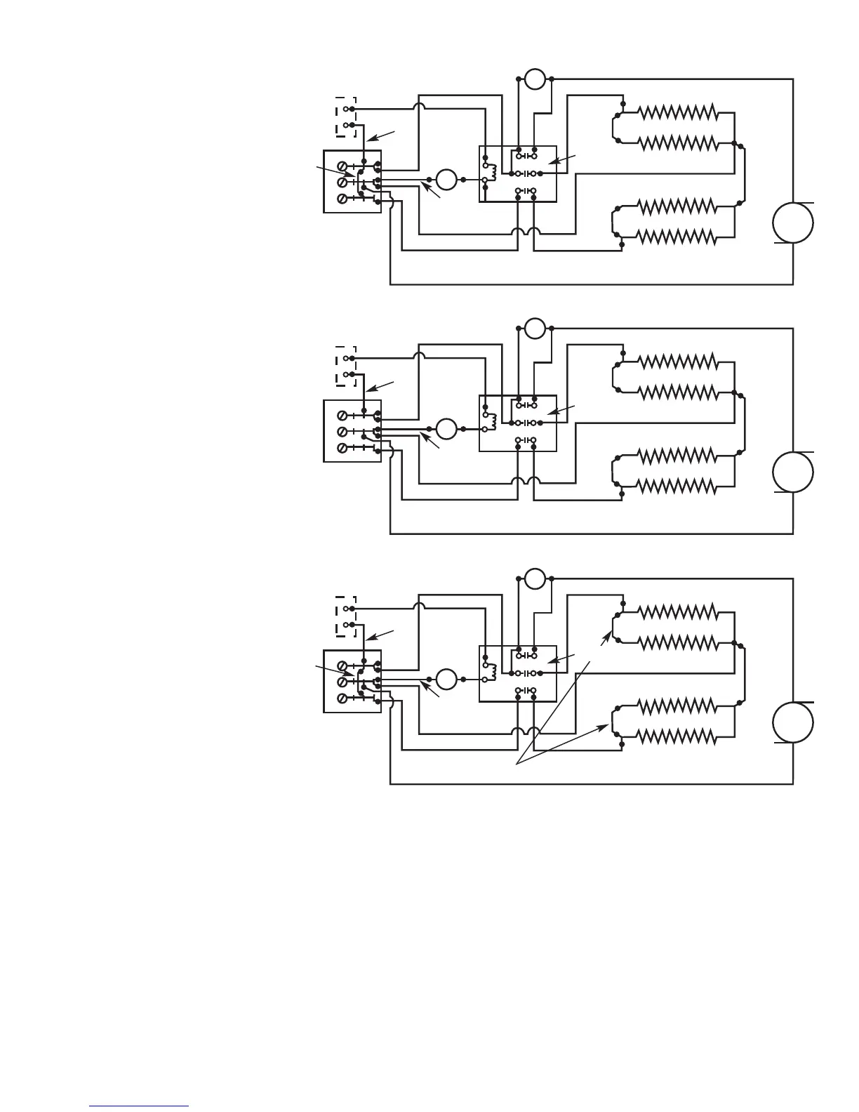
Conversion for 3Ø Installation
Heater is factory wired for connection to 1Ø only. To convert to
3Ø, remove and discard blue jumper wire between L1 & L3.
(Figure 13).
7
FFiigguurree 1133 –– EElleeccttrriiccaall WWiirriinngg
Blue
Optional Field Installed Wall
Thermostat SPST or Internal CDFT
Thermostat Accessory
Optional Field Installed Wall
Thermostat SPST or Internal CDFT
Thermostat Accessory
Optional Field Installed Wall
Thermostat SPST or Internal CDFT
Thermostat Accessory
White
Black
White
Black
Black
Black
Black
Black
Black
Blue
Red
Red
Power
Block
High
Limit
Contactor
Blk
Fan Delay
Fan
Element 2
Element 1
Yellow
Yellow
L1
L2
L3
T1
T
2
T3
Standard Wiring Diagram
(Factory Wired)
White
Black
White
Black
Black
Black
Black
Black
Black
Blue
Red
Red
Power
Block
High
Limit
Contactor
Blk
Fan Delay
Fan
Element 2
Element 1
Yellow
Yellow
L
1
L2
L
3
T
1
T
2
T
3
Wiring
Conversion
for 3Ø
Installation
Blue
White
Black
White
Black
Black
Black
Black
Black
Black
Blue
Red
Red
Power
Block
High
Limit
Blk
Fan Delay
Fan
Element 2
Element 1
Yellow
Yellow
L1
L2
L3
T1
T2
T3
Wiring
Conversion
to Lower
Wattage
(1Ø)
Remove One (1) Red Jumper to Obtain 3/4 Nameplate Wattage
Contactor
Wiring Diagrams