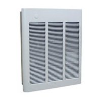
Adjustable Discharge Grilles Custom Air Flow
Patterns (Figure 12)
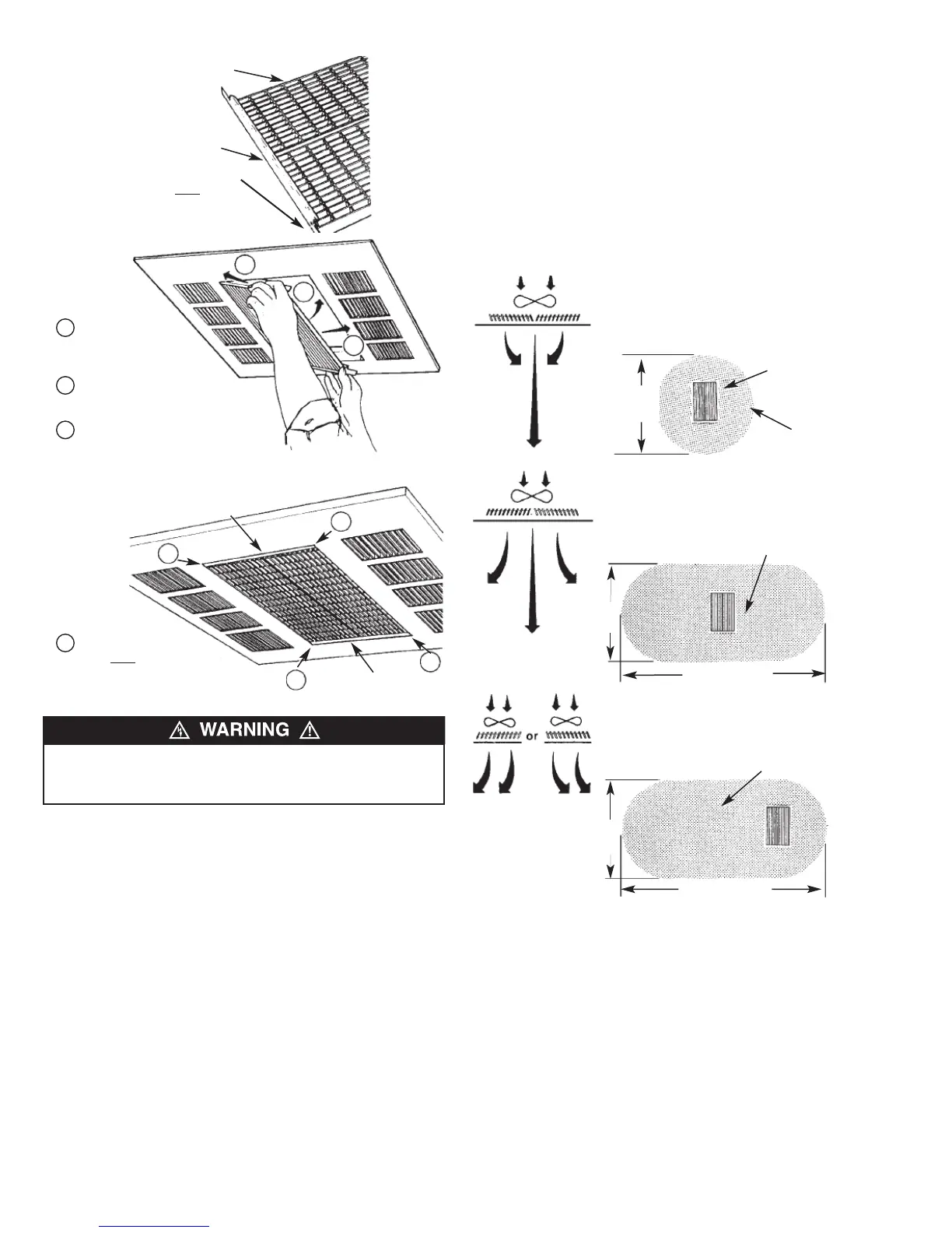
1. The discharge air pattern is deter mined by the arrangement
of the discharge grilles.
2. Care must be taken when selecting location of heater. Refer
to “Installation of Discharge Air Grilles”, page 5.
Note: The discharge grill area is rectang ular; the discharge
grilles can only be installed parallel to the intake louvers.
TO PREVENT THE DISCHARGE GRILLE GUIDES FROM
FALLING, THE GUIDES MUST BE FITTED (LOCKED) IN
POSITION AS SHOWN IN FIGURE 12.
1
2
3
Slide grille assembly
into opening far enough
to clear louver ends.
Push grille assembly up
into opening.
Slide grille assembly
into position in opening.
1
2
3
FFiigguurree 1100
FFiigguurree 1111
Bottom of each louver
guide Must
lock in
position in opening.
1
1
1
1
1
Louver Guide
Louver Guide
Discharge Grille (2)
Louver Guides
Tabs on Discharge
Grilles Must
Face
Upward
F
F
i
i
g
g
u
u
r
r
e
e
9
9
DDiisscchhaarrggee AAiirr
GGrriillllee AArrrraannggeemmeenntt
CCuussttoomm AAiirr
FFllooww PPaatttteerrnn
NARROW AIR PATTERN for high ceiling applications
(11’ (3352 mm) to 14’ (4267 mm)), concentrates the
heated air to ensure full penetration to the floor level.
8’
(2438 mm)
Heater Discharge
Grilles
Air Pattern on Floor
WIDE AIR PATTERN for standard ceiling applications
(8’ (2438 mm) to 10’ (3048 mm)), disperses the air to
give a gentle, less pronounced pattern while circulat-
ing all the air from floor to ceiling.
8’
(2438 mm)
Air Pattern on Floor
ASYMMETRICAL AIR PATTERN directs heated air in a
specific direction, allowing the heater to be located
where space allows with the heated air delivered to
where it is required.
10’
(3048 mm)
Air Pattern on Floor
24’ (7315 mm)
17’ (5181 mm)
FFiigguurree 1122
6