Service Manual - DVH 09/12/18/24 SF Series
Service Manual - DVH 09/12/18/24 SF Series
9.2 Outdoor unit board components and error codes
For A-DVH09SF-0, A-DVH12SF-0
Service Manual - DVH 09/12/18/24 SF Series
9.2 Outdoor unit board components and error codes
For A-DVH09SF-0, A-DVH12SF-0
29
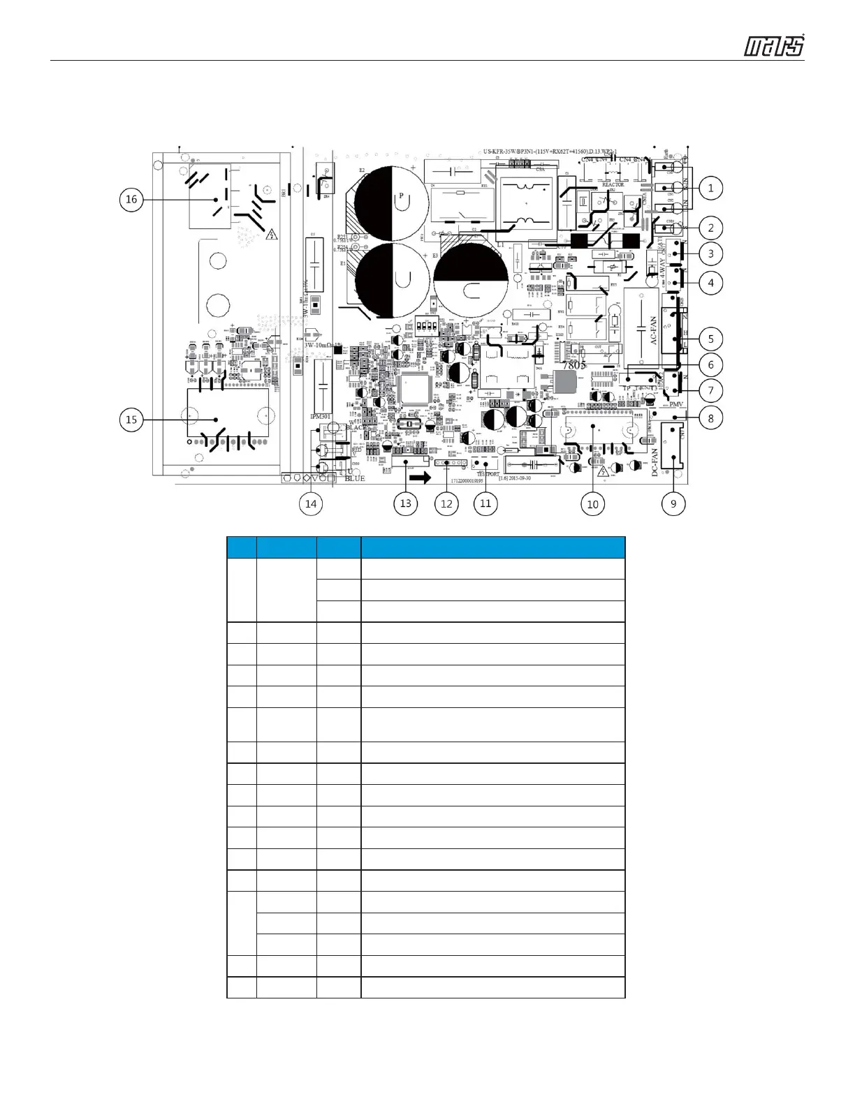
Outdoor unit printed circuit board diagram: 17122000019195
No. Name CN# Meaning
1 Power Supply
CN3 Earth: connect to Ground
CN1 N_in: connect to N-line (100-130V AC input)
CN2 L_in: connect to L-line (100-130V AC input)
2 S CN16 S: connect to indoor unit communication
3 HEAT1 CN17 connect to compressor heater, 100-130V AC when is ON
4 4-WAY CN60 connect to 4 way valve, 100-130V AC when is ON.
5 AC-FAN CN25 connect to AC fan
6 TP T4 T3 CN21
connect to pipe temp. sensor T3, ambient temp. sensor T4, exhaust
temp. sensor TP
7 HEAT2 CN15 connect to chassis heater, 100-130V AC when is ON
8 PMV CN31 connect to Electric Expansion Valve
9 DC-FAN CN7 connect to DC fan
10 FAN_IPM IPM 501 IPM for DC fan
11 TESTPORT CN6 used for testing
12 EE_PORT CN505 EEPROM programer port
13 MCUPORT CN507 connect to PC communication
14
W CN28 connect to compressor
V CN29 0V AC (standby)
U CN30 10-230V AC (running)
15 COMP_IPM IPM 301 IPM for compressor
16 BR1 BR1 Bridge
 Loading...