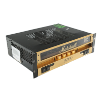
9100 and 9200 valve power
amplifiers
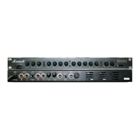
1. Channel A mains power rocker switch
Connects channel A to incoming mains supply.
LED 3 indicates red when activated.
2. Channel A standby switch
Connects channel A's high voltage circuit to the
power supply. LED 4 indicates green when
activated.
Note! Items 1 & 2 are marked 0 &1 (to comply
with international regulations), 0 is off and 1 is on.
Note! To conserve valve life, standby switch 2
should remain off for at least 1 minute after
powering up the amplifier.
3/4. Mains & standby LED's.
5. Voice B LED -
Indicates red when channel A's voicing option B is
activated.
6. Channel A voice toggle switch
Selects voice option A or B, this function is
repeated on a remote switching jack on the rear
panel (see rear panel functions). The switch should
be in the B position for the remote switch to be
operative.
7. Channel A presence control
Rotary control to boost the upper mid to high
frequency content of sound.
8. Channel A gain control
Rotary control to set and balance the incoming
signal level.
9. Channel B gain control
10. Channel B presence control
11. Channel B voice switch
12. Channel B voice LED
13. Channel B standby LED
14. Channel B mains LED
15. Channel B standby switch
16. Channel B mains switch
Note! Channel A's notes also apply.
17. Upper front panel fixing screws
Use 2mm (5/64) allen head driver to remove.
18. Front rack mount fixing holes.
Rear Panel
1. Mains input socket
Connects amplifier to incoming mains supply.
3
A
B
9200
Dual MonoBloc Amplifier
1 2 3 4 5 6 7 8 9 10 11 12 13 14 15 16 17 18
1 23 45 6 7 8 9 101112131415