CV605-U3 Manual
www.marshall-usa.com3 4
2. USB3.0 Type-C output: Use the included USB cable to connect camera to computer USB3.0 port,
then run whichever video capture software chosen on computer and select the camera to display
image.
3. HDMI output: Use HDMI cable to connect camera to a monitor or switching equipment, then the
monitor or other processing equipment will display image.
2. Product Overview
2.1 Product Introduction
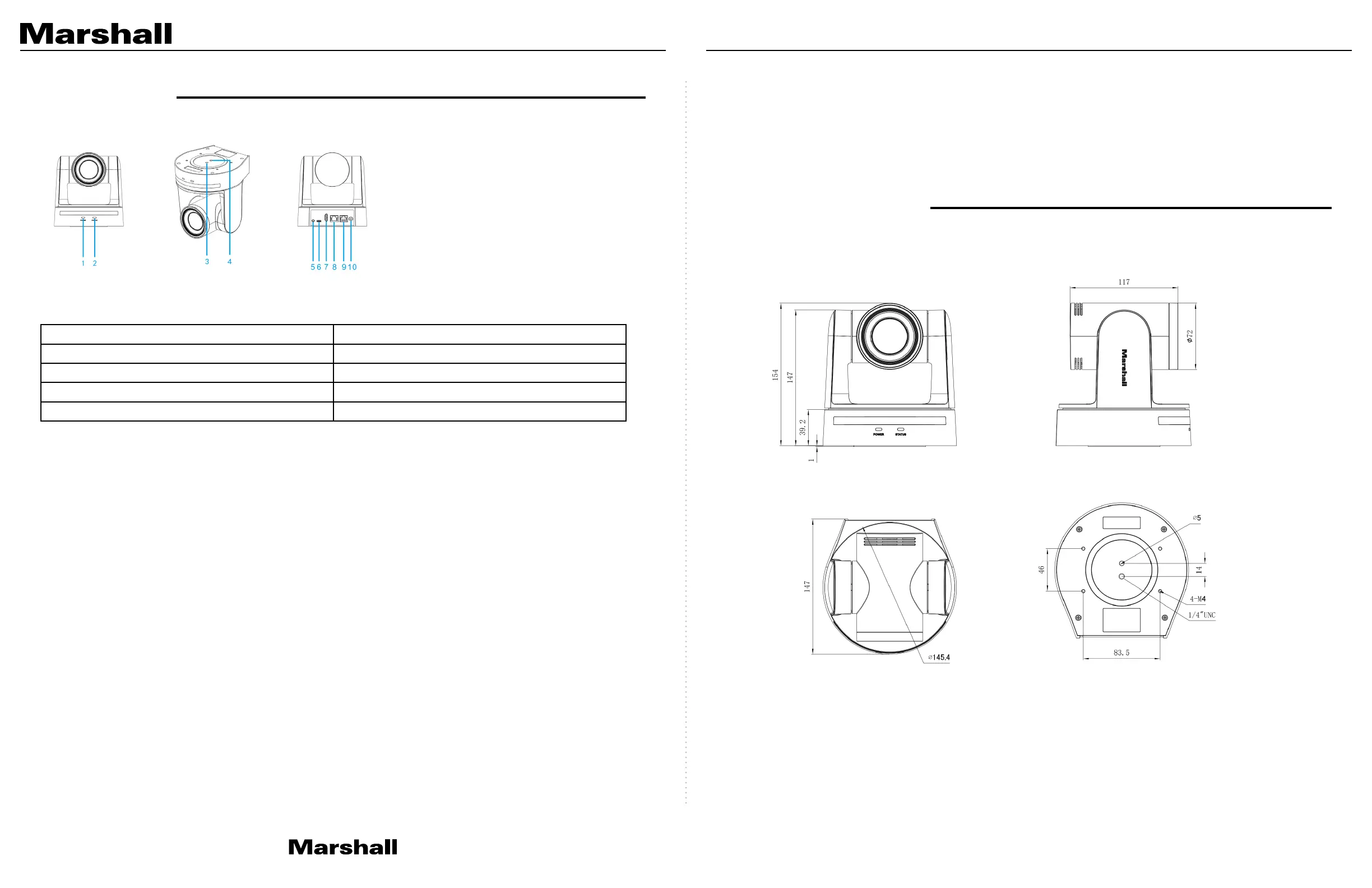
2.1.1 Camera Dimensions
2.1.2 Accessory
During unboxing of camera packaging, please check that all the supplied accessories are included:
Accessories:
• Power adapter
• IR Remote
• USB3.0 Type-C Cable
• Thank You Card
• Warranty card
1. Installation
1.1 Camera Layout
Layout Definitions of USB3.0 Type-C Model:
1. Power Indicator 2. Remote Controller Receiver Light
3. Stability Hole Mount 4. ¼”-20 Mounting Hole
5. Audio Input interface 6. USB3.0 Type-C interface
7. HDMI Port 8. Ethernet Port
9. RS232 Port 10. DC12V Input Power Supply Socket
1.2 Power on initial configuration
1. Power on: Connect DC12V power supply included in box to power outlet and camera power input.
2. Initial configuration: Once powered up the power indicator light will start blinking, camera head will
move from bottom left then moves to the HOME position (horizontal and vertical center), while the
camera module boots up. As soon as remote-control receiver light stops blinking, the self-check
and boot up is complete.
Note:
• The default address of the IR remote is Camera #1 address.
• If you set preset to “0” then after self-check and boot-up, the camera will then automatically move
to the preset “0” position that you’ve chosen as start position.
1.3 Video Output
1. Network output:
A. Network Cable Connection Port: No.8 in Figure 1.1
B. Webpage Login: : Open web browser and enter default IP address 192.168.5.163 in the address
bar (factory default); press Enter and enter the LOGIN prompt. Then click on default user name
admin and password admin (factory default); then press Enter to see preview page. Users
can carry out PTZ control commands, playback, configuration and other operations from this
software GUI.
Optional Accessories (sold separately):
• CV605-WM (Wall Mount-Black)
• CV605-WMW (Wall Mount-White)
• CV605-CM Ceiling Mount (one color)
 Loading...