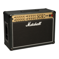
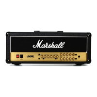
Do you have a question about the Marshall Amplification JVM 4 Series and is the answer not in the manual?
Details on connecting to the mains power supply and the importance of the correct fuse.
Procedures for safely switching on the amplifier for use with speakers or for silent recording.
Steps for connecting and operating the amplifier with external speaker cabinets.
Instructions on how to use the amp for recording without a speaker load.
Guidelines for safely moving the amplifier and its components.
Controls the main power to the amplifier, turning it on and off.
Used in conjunction with the power switch to warm up the amp before use.
Dual function switch for entering footswitch or MIDI program modes.
Engages/disengages the serial/parallel FX loop for the current channel.
Connects your guitar to the amplifier using a ¼" jack instrument cable.
Allows selection of channels and cycling through their 3 modes (Green, Orange, Red).
Describes the Clean channel modes: Green, Orange, and Red, detailing their sonic characteristics.
Details the Crunch channel modes: Green, Orange, and Red, highlighting their gain and tonal qualities.
Explains the OD1 channel modes: Green, Orange, and Red, focusing on gain stages for rock and metal tones.
Covers the OD2 channel modes: Green, Orange, and Red, optimized for high gain and modern metal sounds.
Describes the digital reverb routing and its effect on the signal.
Switches the reverb effect on or off for the currently selected channel.
Adjusts the reverb level for the clean channel.
Adjusts the reverb level for the crunch channel.
Adjusts the reverb level for the OD1 channel.
Adjusts the reverb level for the OD2 channel.
Controls the overall volume of the amp across all channels.
Primary master volume control, used by default on all channels/modes.
Secondary master volume control that can be assigned to specific channels/modes.
Allows switching between Master 1 and Master 2 for different volume settings.
Adjusts high frequencies of the power amp for added bite.
Adjusts low frequencies of the power amp for increased bottom end.
Connection point for the supplied mains power lead.
Protects the amplifier and supply in case of a fault.
Programmable FX loop located after the pre-amp, before reverb and serial loop circuits.
Connects external FX equipment to send the signal out of the amp.
Returns the signal from external FX equipment back into the amp.
Configures the loop for professional (+4dBu) or guitar level (-10dBV) equipment.
Controls the amount of external effect mixed with the dry signal.
Outputs the pre-amp signal for external processing or connection.
Connects an external preamp to use the JVM's power section.
Engages/disengages the power amp insert/serial loop.
Provides a pre-master volume, speaker-emulated signal for recording or connection to PA.
Connects the supplied footswitch using a standard ¼" jack instrument lead.
1/4" jack outputs for connecting speaker cabinets with specified impedance ratings.
Connects external MIDI equipment to the amplifier's MIDI In DIN socket.
Outputs a copy of the MIDI signal for daisy-chaining other MIDI equipment.
Procedure for saving amp settings as MIDI presets using the footswitch/MIDI program switch.
Details MIDI channels, note numbers, program changes, and supported modes.
Details the 6-way programmable footswitch and its LED indicators for channels and modes.
Assigns footswitch buttons to recall specific front panel functions instantly.
Programs footswitch buttons to recall complete channel setups and combinations.
Instructions on how to enter programming mode and map functions to footswitch buttons.
Procedure to save the current amp status to a footswitch as a preset.
Procedure to map a specific front panel function to a footswitch.
Procedure to erase all MIDI presets and reset the MIDI reception channel to #1.
Procedure to reset the footswitch to its factory default settings and function.
| Brand | Marshall Amplification |
|---|---|
| Model | JVM 4 Series |
| Category | Amplifier |
| Language | English |
