WARNING: THE HEARTH EXTENSION AND THE
METAL SAFETY STRIP SHOULD BE INSTALLED
ONLY IN A HORIZONTAL RELATIONSHIP TO THE
FIREPLACE, AS ILLUSTRATED.
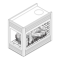
METAL
SAFETY STRIP
HEARTH EXTENSIONS
FLOOR LINE WITH RAISED HEARTH
TOP OF
RAISED HEARTH
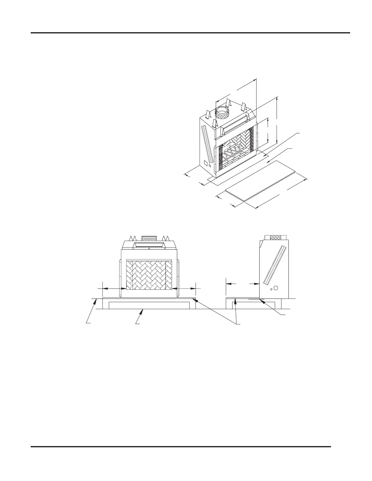
12" (MIN)
20"
(MIN)
12" (MIN)
METAL
SAFETY
STRIP
58"
30"
74"
COMBUSTIBLE
FLOOR
59"
28 1/2"
20"
HEARTH
PROTECTOR
FIGURE 13
FIGURE 12
The ability of insulating material to retard the transfer of heat may be expressed as either Thermal Conductance
(C), Thermal Conductivity (K), or Thermal Resistance (R). The mathematical relationship of these values and
the formulas for converting one value to another is as follows:
C=K divided by the material thickness2
(Example C = .43 divided by 1/2 (.50)
C = .86)
K = C multiplies by the material thickness
(Example K = .86 multiplied by 1/2 (.50)
K = .43)
R= The material thickness divided by K
(Example R = 1/2 (.50) divided by .43
R = 1.16)
FLOOR PROTECTION
With either type hearth extension minor shifting of the supporting floor or expansion and contraction may even-
tually cause a crack to develop between the hearth extension and the face of the fireplace. To help prevent the
crack from developing, the hearth extension materials must be firmly fastened in place. Wall ties should be
screwed to the face of the fireplace and imbedded in the mortar joints of brick, stone, or other non-combustible
materials. The metal safety strip packed with the fireplace must be placed beneath the fireplace and extended
under the hearth extension or into a mortar joint of the hearth extension as shown by Figures 10, 12, and 13. In
the event a crack does eventually develop, the metal safety strip will serve as a barrier to prevent sparks or
embers from falling from the fireplace onto combustible flooring materials.
10
53D9027. Rev 1 03/03
 Loading...