4
Electrical connection
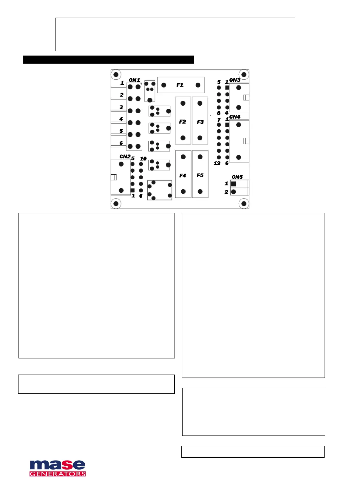
CN1
1 – START relay
2 – Positive battery
3 – Positive battery
4 – Common START relay, Stop solenoid, glow plug,
insulated poles
5 – Negative battery
6 – Negative battery
CN2
1 – Glow plug relay
2 – Stop solenoid relay
3 – Insulated poles relay
4 – Positive battery
5 – Negative battery
6 – START relay
7 – Input D+
8 – Input oil pressure
9 – Input engine temperature
10 – Input high alternator temperature
CN3
1 – Negative battery
2 – Negative battery
3 – #
4 – #
5 – Resistance bridge RS485
6 – B RS485
7 – A RS485
8 – Resistance bridge RS485
CN4
1 – Input Emergency
2 – Input wake up board (- batt)
3 – Input manual start (- batt)
4 – Negative battery
5 – Positive battery
6 – Positive external battery
7 – Input “stop + reset” (- batt)
8 – #
9 – RUNS relay
10 – ALARMS relay
11 – Common relay ALARMS e RUN
12 – Negative external battery
Voltage supply:
12 Vdc
FUSE 5A 5x20 glass
F1 – Output relay Run ((9-CN4)
F2 – Output relay Insulated poles (3-CN1)
F3 – Output relay Common alarms (10-CN4)
F4 – Output relay Glow plugs (1-CN2)
F5 – Output Stop solenoid (2-CN2)
Coin cell Battery 3Vdc type BR 1225