INTRODUCTION
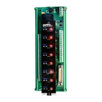
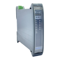
The Linearized RTD/TC module is flexible for DIN rail
mounting and is easily installable. The module has wide
input & output ranges, which are field selectable & factory
settable as per customer requirement respectively.
SAFETY AND WARNING NOTES
To minimize potential shock, turn off power to module
installed in the base before inserting or removing a
module.
In order to make safe operation of the device and to be
able to make use of all the functions, please read these
instructions thoroughly!
The device may only be installed and put into operation by
qualified personnel.
SPECIFICATIONS
Input:
No. of Channel : 8
Input (Field Side)* : RTD: PT 100 3-wire (0.1 ºC)
(Automatic 3 wire Compensation)
TC: E, J, K, T, B, R, S, N (ANSI
Standard).
Input Range : Refer Table2
Input Impedance : >1M
Input Resolution : 16 Bits
Burnout Current
for TC : <1uA
CJC Error :
+/-2.0Deg.
RTD Excitation
current : 0.3048 mA
Minimum Spans : TC: 5 mV
PT100: 50ºC
LED Indication : Green Color: Healthy Signal Presence
: Blinking LED: sensor OPEN Indication
Output:
O/P : Voltage / Current
(Module Side) **
O/P range ** : Voltage: 0 to 5 V
0 to 10 V
1 to 5 V
Current: 4 to 20 mA
0 to 20 mA
Sensor break o/p* : Upscale / Downscale
Output direction* : Direct / reverse
Response Time : ≤ 500 mili second at full load
Drift : 0.2% per Year
O/P connection ** : MKDS or D type connector.
Load Resistance : <750 Ω (for Current)
>4.7K Ω (for Voltage)
Accuracy : 0.25% Full Span ±1 Degree
O/P Resolution : 0.005% of full span
Power supply:
Power : 24VDC ±10%
Fuse Rating : 2Amp (Fast Blown)
LED Indication : Green LED – Healthy Status
Red LED – Fault Status
Isolation : 1.5KV AC
Input to Power, Input to Input,
Output to Power
Environmental:
Operating Temp. : Operating at 0 to 50°C
Tempco : ≤ 150 PPM
Humidity : 30 to 95% RH non- condense
Environmental
Protection : Conformal Coating on PCB
CMRR : >120dB
NMRR : >40dB
Terminal:
Terminal Block : 2.5mm² conductor size
Calibration:
1) Zero and Span calibration through mTRAN
2) CJC for TC type input and 3-wire compensation for
RTD sensor is automatic.
3) Instrument Warm up time approx. 30 min
Mechanical:
Size: 225mm x 90mm x 91.3mm
* Selectable through mTRAN configuration software.
**Factory settable as per customer requirement.
-200 to 850 ºC
Table 2: Input (Field Side)
PRODUCT ORDER CODE
For Input: Pt-100 and Output: 4-20mA with D-Type
connector at output side.
Model: MAS-AI-U-08-D-9-1-1
Model Input Type &
Range
Output Type &
Range
Output
Connection
MAS-
AI-U-
08-D
X X X
1 E 1 4-20mA 0 PCB
Terminal
Block
2 J 2 0-20mA 1 D Type
Connector
3 K 3 1-5VDC
4 T 4 0-5VDC
5 B 5 0-10VDC
6 R
7 S
8 N
9 Pt-100
Table1: Product Ordering Code
At the time of ordering, specify the input range within the
ranges as per reference Table 2
INSTALLATION GUIDELINES
This Module is suitable for mounting on 35mm DIN
Rail. Note the polarity when connect field wire.
The (horizontal) mounting arrangements shown here,
allows good vertical air circulation. It is also recommended
to keep adequate gap between two modules.