Do you have a question about the Masibus MINT-AOV-08 and is the answer not in the manual?
Provides important information to prevent damage and ensure safe product usage.
States manual is for qualified personnel; safety instructions and legal regulations must be followed.
Outlines required professional qualifications for installing, configuring, and removing mINT IOs.
Provides Modbus register addresses for configuring COM1 and COM2 parameters.
Categorizes Modbus variables by type and access method (Read/Write).
Guides users on accessing and configuring mINT CP parameters via web pages.
Discusses how data is organized and accessed within the mINT CP.
Explains how mINT IOs are addressed and configured based on their variables.
Lists addresses for configuring serial and Ethernet communication parameters of the mINT CP.
Details addresses for reading diagnostic data of the mINT CP.
Explains how to configure Direct IO via Ethernet using a base address.
Describes Direct IO configuration for USB slave ID-127.
Details how input signals are processed, including latching and counter registers.
Describes how an ON state is latched when an OFF input transitions to ON.
Describes how an OFF state is latched when an ON input transitions to OFF.
Explains the structure of counter registers for capturing count values.
Explains how to capture counter values into registers.
Describes registers that display stored counter values in non-volatile memory.
Details how to set the initial counter value to zero upon power ON.
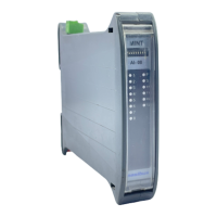
| Type | Analog Output Module |
|---|---|
| Number of Outputs | 8 |
| Output Type | Voltage/Current |
| Power Supply | 24 VDC |
| Output Voltage | 0-10 V |
| Operating Temperature | 0 to 55 °C |
| Protection Class | IP20 |
| Communication Protocol | Modbus RTU |
| Humidity Range | 5% to 95% RH, non-condensing |