Do you have a question about the Masibus MINT Series and is the answer not in the manual?
Details manual content and design principles.
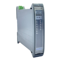
Introduces the mINT IO product line and its features.
Explains how to identify and order specific product configurations.
Lists accessories provided with the product.
Outlines critical safety instructions for product use and installation.
Details module size, mounting, and DIN rail compliance.
Explains proper grounding and shielding for interference reduction.
Details RS485 wiring and cabling methodology for reliable communication.
Covers DIP switch settings for Node ID and RS-485 termination.
Explains default and programmable communication settings for modules.
Introduces the mINT CP as a Modbus TCP to serial gateway.
Lists electrical and communication specs for the mINT CP module.
Explains configuration via mINT-Plus software and web browser.
Details power supply connection and Ethernet network configuration.
How to connect the mINT CP directly to a PC using an Ethernet cable.
Connecting the mINT CP to a network or hub for access.
Accessing the web interface to configure IP, Gateway, and Subnet Mask.
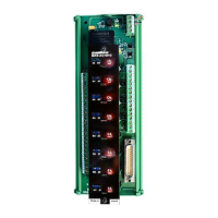
Illustrates the internal components and connections of the mINT CP.
Explains how data is addressed and mapped within the mINT CP.
Details Modbus addresses for configuring serial and Ethernet parameters.
Configuration registers for IP address, subnet mask, and gateway settings.
Configuration addresses for Modbus TCP port and communication timeouts.
Describes the types of variables accessible via Modbus protocol.
Lists Modbus addresses for accessing diagnostic data of the mINT CP.
Introduces the 16-channel digital input module and its features.
Lists electrical, input, environmental, and communication specs for the module.
Explains the meaning of LEDs on the mINT-16DI module for status indication.
Shows how to wire the digital inputs to the module's terminals.
Details filter time and debounce time for input signal processing.
Explains counter registers, capture, and zero settings for counting inputs.
Introduces the 16-channel digital output module and its operational modes.
Lists electrical, output, environmental, and communication specs for the module.
Explains the meaning of LEDs on the mINT-16DO module for status indication.
Shows typical wiring for connecting outputs to external loads like relays.
Sets the initial output state upon module power-up.
Configures the output mode (Discrete, Single Pulse, Continuous Pulse).
Defines the duration of high and low levels for pulse outputs.
Introduces the 8-channel universal analog input module and its selectable inputs.
Lists input types, resolution, accuracy, and environmental specs for the module.
Explains the meaning of LEDs on the mINT-08AI module for status indication.
Shows how analog inputs are connected to the module's terminals.
Lists Modbus addresses for configuring analog input parameters.
Introduces the 8-channel analog output module and its fixed output types.
Lists output types, resolution, accuracy, and environmental specs for the module.
Explains the meaning of LEDs on the mINT-08AO module for status indication.
Shows how analog outputs are connected to the module's terminals.
Lists Modbus addresses for configuring analog output parameters.
Introduces mINT-PLUS software for module configuration and diagnostics.
Lists addresses and parameters for software-based diagnostics.
Instructions for securely mounting and removing the enclosure from a DIN rail.
Details conductor cross-section and AWG requirements for electrical connections.
How mINT IO modules expand PLC/HMI I/O capabilities using RS485.
Using mINT IO modules for data acquisition with PCs and SCADA systems.
Connecting IO modules to a common communication processor via Ethernet.
A visual guide to diagnose and resolve common issues with the instrument.
Provides essential contact information for technical support and service inquiries.
| Brand | Masibus |
|---|---|
| Model | MINT Series |
| Category | Control Unit |
| Language | English |