Page | 45
MINT – IO
REF NO: m25A/om/101
Issue No: 11
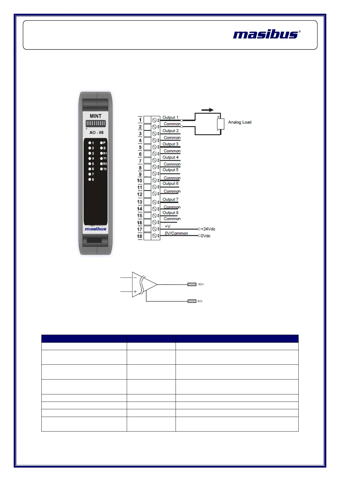
4.4.4 Wiring Diagram:
The following diagram shows how the Analog Outputs are connected to the
Output Terminals.
Equivalent Circuit Diagram:
4.4.5 Modbus Address for configuration:
Channel 1 – 8 Outputs – Read Only
Process Value (Swap
Float)
Channel 1 – 8 Outputs – Read Only
Ambient Temperature
(INT)
Ambient Temperature Read Only
Ambient Temperature
(swap Float)
Ambient Temperature Read Only
Channel 1 – 8 Output Types
Channel 1 – 8 Output Apply – 16 Bit
Ambient Temperature Calibration (0°C –
55.0°C)
 Loading...