Page | 29
MINT – IO
REF NO: m25A/om/101
Issue No: 11
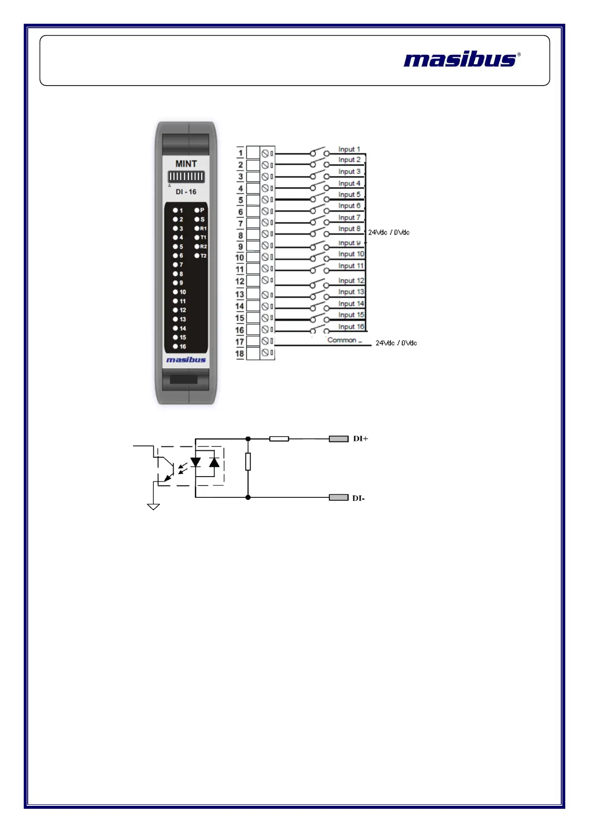
4.1.4 Wiring Diagram for mINT – 16DI – Digital Inputs:
Equivalent Circuit Diagram:
4.1.5 Input Processing – Filtration
4.1.5.1 Latch High:
If the channel is in the OFF state and then the ON signal is received, the ON
state will be latched. This state continues until it is forced OFF by user
4.1.5.2 Latch Low:
If the channel is in the ON state and then the OFF signal is received, the OFF
state will be latched. This state continues until it is forced OFF by user.
4.1.5.3 Counter Registers:
The counter registers display two 16 bit registers. The first register is the High
Register and the second register is the Low Register. To get the actual 42 bit
count value the registers must be combined as follows:
Counter High Value = Register 40001.
Counter Low Value = Register 40002.
Counter Value = (Counter High Value X 65535) + Counter Low Value.
 Loading...