Page | 41
MINT – IO
REF NO: m25A/om/101
Issue No: 11
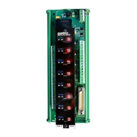
4.3.4 Wiring Diagram:
The following diagram shows how the Analog Inputs are connected to the
Input Terminals.
* 50 ohms
Connected
Outside
4.3.5 Modbus Address for configuration:
Channel 1 – 8 Inputs – Read Only
Process Value (Swap Float)
1
Channel 1 – 8 Inputs – Read Only
Ambient Temperature (INT)
Ambient Temperature Read Only
Ambient Temperature (Swap Float)
Ambient Temperature Read Only
Channel 1 – 8 Input Types
Channel 1 – 8 Input User Zero
Channel 1 – 8 Input User Span
Calibration Ambient
(Password Protected) - Factory Use
Ambient Temperature Calibration
(0°C – 55.0°C)
Decimal Points for Floating Values
(only for Voltage & Current Inputs)
0-xxxxx, 1-xxxx.x, 2-xxx.xx
3-xx.xxx, 4-x.xxxx, 5-0.xxxxx
* Calibration is used for factory purpose, these parameters are not recommended to use on field.
 Loading...