Page | 15
MINT – IO
REF NO: m25A/om/101
Issue No: 11
3.1.3 Status Indicators
1. Power supply: indicates power supply is been provided.
2. Status: Indicates healthy condition of microcontroller.
3. Diagnostic: Indicates direct configuration with CP or IO.
4. Memory: Indicates data communication with flash memory
5. Uart-1 Rx: Indicates data received at com port 1
6. Uart-1 Tx: Indicates data transmitted from com port 1
7. Uart-2 Rx: Indicates data received at com port 2.
8. Uart-2 Tx: Indicates data transmitted from com port 2.
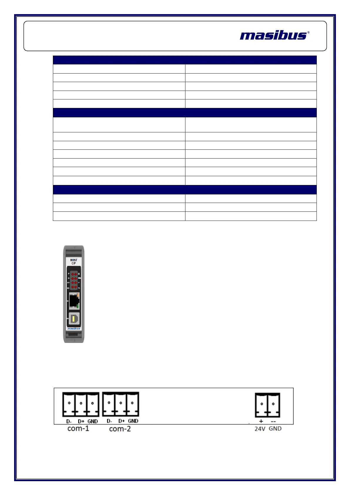
3.1.4 Wiring
Following diagram shows the wiring of the power supply and RS-485
Connection.
Performance Specifications
Maximum No. of Read Registers
Maximum No. of Write Registers
Configuration and Diagnostics
Serial Port Specifications:
RS485 port 1 & 2 (D+, D-, GND) (2-wire
half-duplex)
Communication Speed(Baud rate)
9600, 19200, 38400, 57600,115200 bps.
Environmental Specifications:
Humidity (Non-condensing)
 Loading...