Page | 48
MINT – IO
REF NO: m25A/om/101
Issue No: 11
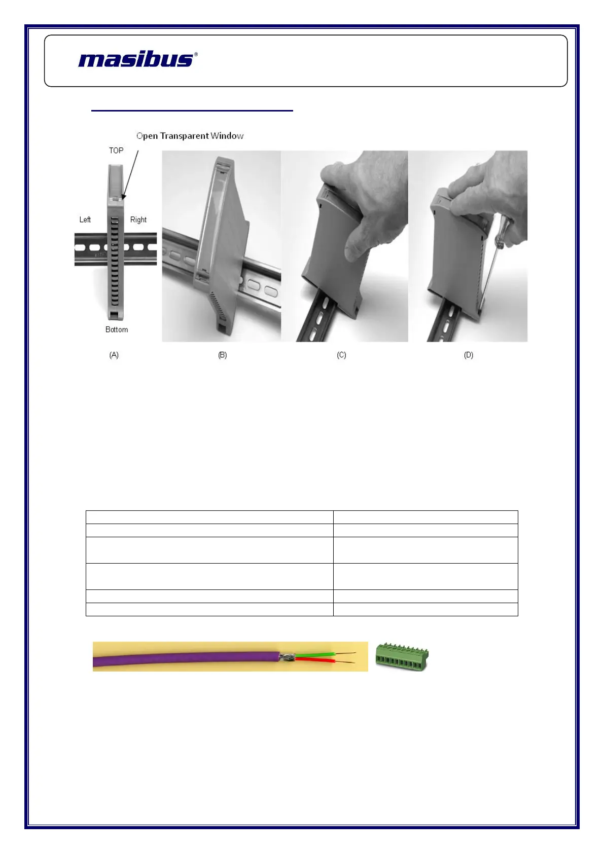
6. MECHANICAL GUIDELINES
Fig <B> Electronic equipments usually have the DIN rail mounting hook at the
bottom; therefore we maintained this standard
For the MINT Series
Fig <C> How to mount the enclosure on the DIN rail: insert the upper part of
the enclosure onto the DIN rail and press until
The Hook clicks itself
Fig <D> How to remove the enclosure from the DIN rail: unhook the lower part
using a screw driver and lift the enclosure from the DIN rail.
6.1 Cable data
Conductor cross section solid
Min. 0.14 mm² & Max. 1.5 mm²
Conductor cross section stranded
Min. 0.14 mm² & Max. 1.5 mm²
Conductor cross section stranded, with ferrule
without plastic sleeve
Min. 0.25 mm² & Max. 1.5 mm²
Conductor cross section stranded, with ferrule
with plastic sleeve
Min. 0.25 mm² & Max. 0.5 mm²
Conductor cross section AWG/kcmil
 Loading...