Page | 36
MINT – IO
REF NO: m25A/om/101
Issue No: 11
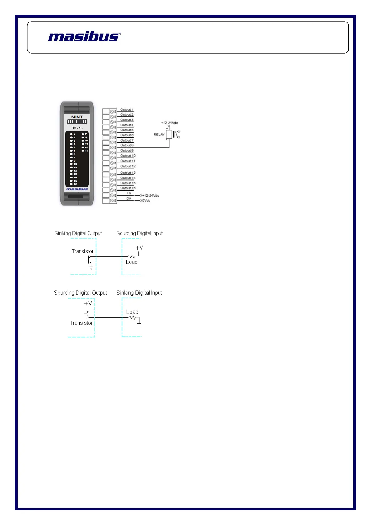
4.2.4 Wiring Diagram:
The following diagram shows how the digital outputs are connected to the coil
of a relay. (Typical Output Diagram)
Equivalent Circuit Diagram: Sink Output (0V)
Equivalent Circuit Diagram: Source Output (+24V)
4.2.5 Configurable Parameters
Using mINT PLUS the following attributes can be configured to suit the
required operation of this Module.
4.2.5.1 Predefine Value:
This parameter is the value set to each channel on power-up of the module,
e.g. “1” or “0”. This Value is user defined and can be configured for each
channel. This parameter can have the following
Values: 0, 1
The factory default is “0” for this parameter.
 Loading...