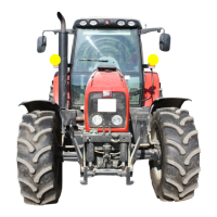
Massey Ferguson 6400 - Issue 1
02C01.4
Splitting - GBA20 gearbox / Centre housing
12. Mark then disconnect:
- the electrical connectors on the selector cover,
the control unit (Dynashift – reverse shuttle) and
the right-hand hydraulic cover.
- the radar (if fitted).
Servicing on the left-hand side of the
tractor
13. Mark then disconnect:
- the hose on the steering ram
- the harness of the fuel gauge on the tank
- the gas oil feed and return hoses on the engine
(block ports immediately)
- the vent hose on the tank
14. Drain the tank (if necessary) and remove it.
15. Disconnect the transmission lubricating pipe or
hose located at the front left-hand side of the
gearbox.
Servicing under the cab
16. Mark, toe-in and disconnect the heating hoses,
immediately blocking the ports.
Servicing on the engine
17. Disconnect the connector of the main engine
wiring harness.
18. Disconnect the throttle control cable on the injec-
tion pump (4-cylinder engine only).
19. Separate the compressor, the condenser and the
filter from their respective holders, and remove
them carefully, without breaking the circuit.
Remark
Work carefully.
Preparing for disassembling
20. Cancel the front axle oscillation (all versions) by
sliding an suitable chock in at each side of the
support (1) (Fig. 3).
21. Chock the rear wheels.
22. Place fixed stands (Fig. 5):
- At the front of the centre housing.
- To the rear of the hitch hook.
23. Position a mobile stand at the back of the gearbox
(Fig. 5).
24. Separate the cab from the supports on the front
right- and left-hand sides (fixed or suspended cab
versions – see chapter 12).
25. Gently lift it using two straps fitted to the lateral
handles.
26. Fit a wooden chock temporarily between the cab
and the front supports.
Disassembling
27. Remove each screw (1) fixing the gearbox to the
centre housing (Fig. 4), marking its position.
Screw dimensions
• M14 x 45 mm screw
• M14 x 60 mm screw
• M14 x 70 mm screw
Fig. 3

 Loading...


