6
EMOS spol. s r. o.
7
• Never perform capacitance measurements unless the capacitor to be measured
has been discharged fully.
• Always be careful when working with voltages above 60V dc or 30V ac rms.
Keep fingers behind the probe barriers while measuring.
SYMBOLS
– Important safety information, refer to the operating manual
– Dangerous voltage may be present
– Earth ground
– Double insulation (protection class II)
MAINTENANCE
• Before opening the meter, always disconnect test leads from all sources of
electric current.
• For continue protection against fire, replace fuse only with the specified voltage
and current ratings: F1: F 300mA /250V
• If any faults or abnormalities are observed, the meter can not be used any more
and it has to be checked out.
Never use the meter unless the back cover is in place and fastened fully.
• To clean the meter, use a damp cloth and mild detergent only, do not use
abrasives or solvents on it.
GENERAL SPECIFICATIONS
Max. Voltage Between Terminals
and Earth Ground: 1000V dc or 750V rms ac (sine)
Fuse Protection: µA, mA, F 300mA/250V
Power Supply: 9V battery, NEDA 1604 or 6F22
Display: LCD, 3260 counts max, updated 2-3/sec.
Measurement Method: Dual slope integration A/D converter
Ranging Method: Auto/Manual
Overrange Indication: “OL” displayed
Polarity Indication: “ – ” displayed automatically
Low Battery Indication: “ ” displayed
Operating Temperature: 0°C to 40°C (32°F to 104°F)
Storage Temperature: -10°C to 50°C (10°F to 122°F)
Dimension: 91×189×31.5mm
Weight: 310g (Including battery)
Accuracy is specified for a period of one year after calibration and at 18°C to 28°C
(64°F to 82°F) with relative humidity to 80%.
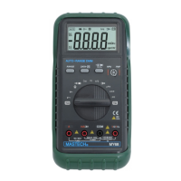
DESCRIPTION
1 Range control button
2 Data hold button
3 AC/DC current or selecting button
4 Socket for transistor test
5 Function switch/power switch
6 V/
Ω
/F input jack
7 COM input jack
8 mA/Cx input jack
9 10A input jack
RANGE CONTROL BUTTON
Range for AC/DC voltage, AC/DC current (µA and mA only), Resistance and Frequen-
cy measuring can be selected manually or handled by autoranging. Push this button
as following to choose range control mode and desired ranges.
DATA HOLD BUTTON
When this button is pushed, the display will show the last reading and “D-H” symbol
will appear until pushing it again.
Data holding will be canceled automatically when the function switch is rotated.
AC/DC CURRENT OR
/
SELECTING BUTTON
Push this button to select AC or DC current measuring function when the function
switch is set at µA, mA, A positions.
Push this button to select
or
measuring function when the function switch
is set at
position.
INPUT JACKS
This meter has four input jacks that are protected against overload to the limits.
During use, connect the black test lead to the COM jack and the red test lead
as shown below:
Function Red lead connection Input limits
DCV/ACV
V/Ω/F
1000V DC or 750V AC
KHz
V/Ω/F
250V DC or rms AC
Ω
/ /
V/Ω/F
250V DC or rms AC
µA/mA
mA/Cx 300mA DC or rms AC
nF/µF
mA/Cx 300mA fuse protected
A 10A 10A DC or rms AC
µA/mA ranges are protected by fuses
OPERATING INSTRUCTION
MEASURING VOLTAGE
1. Connect the black test lead to the COM jack and the red test leas to V/
Ω
/F
jack.
2. Set the function switch at V
or V
~
range to be used and connect test leads
across the source or load under measurement.
3. Read LCD display. The polarity of red connection will be indicated when making
a DC measurement.
DC Voltage
Range Resolution Accuracy
326mV
100
µV ±0.5% of rdg ±2d
3.26V 1mV
±0.3% of rdg ±2d
32.6V 10mV
±0.3% of rdg ±2d
326V 100mV
±0.3% of rdg ±2d
1000V
1V
±0.5 % of rdg ±2d
Input Impedance: 10M
Ω
, more than 100M
Ω
at 326mV range.
AC Voltage
Range Resolution Accuracy
3.26V 1mV
±0.8% of rdg ±3d
32.6V 10mV
±0.8% of rdg ±3d
326V 100mV
±0.8% of rdg ±3d
750V 1V
±0.8% of rdg ±3d
Input impedance: 10 M
Ω
Frequency Range: 40 to 1000Hz, 40 to 200Hz for 3.26V range.
Response: Average, calibrated in rms of sine wave.
MEASUREING CURRENT
1. Connect with black test lead to the COM jack and the red test lead to the mA/Cx
jack for a maximum of 300Ma.For a maximum of 10A, move the red lead to
the A jack.
2. Set the function switch at µA, mA or A range to be used and push
/
~
button
to select DCA or ACA measuring mode.
3. Connect test leads in series with the load in which the current is to be measured.
4. Read LCD display. The polarity of red test lead connection will be indicated
when making a DC measurement.
DC Current
Range Resolution Accuracy Burden voltage
326µA 0.1µA ±1.2% of rdg ±3d 0.5mV/µA
3260µA 1µA ±1.2% of rdg ±3d 0.5mV/µA
32.6mA
10
µA ±1.2% of rdg ±3d
8.0mV/mA
326mA
100
µA ±1.2% of rdg ±3d
8.0mV/mA
10A 10mA
±2.0% of rdg ±5d
0.02V/A
Overload Protection: F 300mA fuse for µA and mA ranges.
AC Current
Range Resolution Accuracy Burden voltage
326µA 0.1µA ±1.5% of rdg ±5d 0.5 mV/µA
3260µA 1µA ±1.5% of rdg ±5d 0.5 mV/µA
32.6mA
10
µA ±1.5% of rdg ±5d
8.0 mV/mA
326mA
100
µA ±1.5% of rdg ±5d
8.0 mV/mA
10A 10mA
±3.0% of rdg ±7d
0.02 V/A
Overload Protection: F 300mA fuse for µA and mA ranges.
Frequency Range: 40 to 1000Hz
Response: Average, calibrated in rms of sine wave.
Power On or Function Changing
Manual Rang Ng
Range Changed
Push button for less
than 1 sec.
Auto Rang Ng
Push button once
“R-H“ displayed
Push button
for over 3 sec.
MEASURING RESISTANCE
1. Connect the black test lead to the COM jack and the red test lead to the V/
Ω
/F
jack (Note: The polarity of the red lead connection is positive “+”)
2. Set the function switch at
Ω
range to be used and connect test leads across
the resistance under measurement.
Note:
a) For resistance above 3.26 M
Ω
, the meter may take a few seconds to stabilize
reading. This is normal for high resistance measuring.
b) When the input is not connected, i.e. at open circuit, the figure “OL” will be
displayed for the overrange condition.
c) When checking in circuit resistance, be sure the circuit under test has all power
removed and all capacitors are fully discharged.
Range Resolution Accuracy
326Ω 0.1Ω ±0.8% of rdg ±3d
3.26kΩ 1Ω ±0.8% of rdg ±1d
32.6kΩ 10Ω ±0.8% of rdg ±1d
326kΩ 100Ω ±0.8% of rdg ±1d
3.26MΩ 1kΩ ±0.8% of rdg ±1d
32.6MΩ 10kΩ ±1.2% of rdg ±2d
Maximum Open Circuit Voltage: 1.3V
MEASURING CAPACITANCE
1. Connect the black test lead to the COM jack and the red test lead to the mA/Cx
jack. (NOTE: The polarity of the red lead connection is positive “+”)
2. Set the function switch at nF or µF position to be used.
3. Connect test leads across the capacitor under measurement and be sure that
the polarity of connections is observed.
Note:
a) When checking in-circuit capacitance, be sure that the circuit has all power
removed and all capacitor are fully discharged.
b) The range control mode in capacitance measurement is manual ranging and
only two ranges (326nF, 32.6µF) are provided.
c) If Range Control Button is used in this function measuring, decimal points may
be at incorrect positions.
d) At the nF range, when the capacitor to be measured is not connected to test
leads, the LCD may not read zero, but a few counts have to subtracted from
measuring results.
Range Resolution Accuracy
326nF 0.1nF
±3.0% of rdg ±5d
32.6µF
10nF
±3.0% of rdg ±5d
MEASURING FREQUENCY
1. Connect the black test lead to the COM jack and the red test lead to the V/
Ω
/F
jack.
2. Set the function switch at the kHz position and connect test leads across the
source or load under measurement.
The input voltage should be between 200mV and 10V rms ac. If the voltage is
more than 10V rms, reading may be out of the accuracy range.
Range Resolution Accuracy
32.6kHz 10Hz
±1.2% of rdg ±5d
150kHz 100Hz
±2.5% of rdg ±5d
Sensitivity: 200mV rms up to 50kHz,1V rms for 50kHz to 150kHz.
CONTINUITY & DIODE TEST
1. Connect the black test lead to the COM jack and the red test lead to the V/
Ω
/F
jack. (NOTE: The polarity of the red lead connection is positive “+”)
2. Set the function switch at
position and push the
button to select
continuity or diode test mode.
3. In continuity testing, if continuity exists (i.e., resistance less than about 50
Ω
),
built –in buzzer will sound.
4. If diode test mode is selected, connect the red and black leads to the anode
and cathode of the diode under test. The forward voltage drop of this diode in
V will be displayed.
TRANSISTOR TEST
1. Set the function switch at hFE position.
2. Identify whether the transistor is NPN or PNP type and locate emitter, base
and collector lead. Insert leads of the transistor to be tested into proper holes
of the testing socket on the front panel.
3. LCD display will show the approximate hFE value at the test condition of base
current 10µA and Vce 3.2V.
ACCESSORIES
SUPPLIED WITH THE MULTIMETER
Test leads: Electric Ratings 1500V, 10A
Battery: 9V, NEDA 1604 or 6F22
Operating Manual
Holster
BATTERY AND FUSE REPLACEMENT
If the sign “
” appear on the LCD display, it indicates that the battery should
be replaced. Remove screws on the back cover and open the case. Replace the
exhausted battery with a new one.
Fuse rarely need replacement and blow almost always as a result of the operator’s
error. Open the case as mentioned above and take the PCB assembly out from the
case. Replace the blown fuse with ratings specified.
WARNING
Before attempting to open the case, be sure that test leads have been disconnected
from measurement circuit to avoid electric shock hazard.
For protection against fire, replace fuses only with specified ratings:
F1: F300mA/250V
MULTIMETR CYFROWY TYPU MY-68
Multimetr cyfrowy typu MY-68 jest miernikiem uniwersalnym z automatycznie wybieranymi zakresami pomiarowymi wyposażonym w wyświetlacz LCD zawierający 3 1/2
cyfry. Przyrząd jest przeznaczony do pomiaru napięcia prądu stałego DC, napięcia prądu przemiennego AC, natężenia prądu stałego DC, natężenia prądu zmiennego AC,
oporu elektrycznego, pojemności, częstotliwości i wykonywania akustycznego testu ciągłości obwodu oraz sprawdzania diód i tranzystorów.
PL
BEZPIECZEŃSTWO
Multimetr został wykonany i sprawdzony zgodnie z normami bezpieczeństwa IEC
1010, wymaganiami bezpieczeństwa dla elektrycznych urządzeń pomiarowych,
klasy bezpieczeństwa II, kategoria wytrzymałości na przeciążenie II. Poniższa
instrukcja zawiera informacje i ostrzeżenia, które muszą być przestrzegane dla
zapewnienia bezpiecznego użytkowania miernika.
Informacje wstępne
Podczas używania urządzenia muszą być przestrzegane wszystkie powszechnie
przyjęte środki ostrożności dotyczące:
• ochrony przed porażeniem prądem elektrycznym;
•
ochrony urządzenia przed niewłaściwym użyciem;
Zgodnie ze standardowymi środkami bezpieczeństwa, gwarancji można udzielić
tylko pod warunkiem używania urządzenia z dołączonymi, oryginalnymi przewo
-
dami pomiarowymi.
Jeżeli będzie to konieczne, przewody te mogą być zastąpione tylko przewodami o
takich samych parametrach a szczególnie izolacji elektrycznej. Przewody zawsze
muszą być sprawne i w dobrym stanie technicznym.
• Odłączaj przewody pomiarowe od wszelkich źródeł prądu elektrycznego przed
każdym otwarciem obudowy miernika
• Nigdy nie używaj miernika ze zdjętą tylną częścią obudowy
• Przy wszystkich pomiarach należy stosować następujący bezpiecznik: F1: F
300mA/250V
• Jeżeli pojawią się jakieś błędy lub wątpliwości w trakcie pomiarów – miernik
należy oddać do sprawdzenia
• Do czyszczenia przyrządu pomiarowego stosujemy wyłącznie miękką szmatkę
zwilżoną słabym roztworem płynu do mycia naczyń. Nie wolno używać rozpuszc-
zalników i środków do czyszczenia o własnościach ściernych.
Podczas pomiarów
• Aby uniknąć uszkodzenia miernika, należy zwracać uwagę na nieprzekraczalne
wartości napięć i prądów, wskazanych dla każdego zakresu pomiarowego.
• Jeżeli miernik podłączony jest do mierzonego obwodu, nie dotykaj zacisków
wejściowych, nawet jeżeli nie są używane;
• Jeżeli nie znana jest uprzednio przybliżona wartość mierzona, nastaw przełącz-
nik funkcji w najwyższej pozycji.
• Odłącz przewody pomiarowe od mierzonego obwodu przed zmianą zakresu
pomiarowego bądź funkcji za pomocą przełącznika obrotowego.
• Podczas pomiarów w odbiorniku telewizyjnym lub zasilaczu impulsowym pa
-
miętaj, iż amplituda impulsów napięciowych może być wysoka i może uszkodzić
przyrząd pomiarowy.
• Nigdy nie mierzyć oporu elektrycznego w zasilanym obwodzie.
MY68-manual - 6 0 - 0 - 0 - K
 Loading...