5 - CONNECTION OF THE LOUDSPEAKERS
The loudspeaker system should be connected to the Speakon or Terminal
connectors ensuring that the polarity is correct. It is very important to use a cable
fitting to the power of the amplifier in order to maintain the high damping factor these
units provide. As a general guideline, we offer a table of the minimum cross section
values according to the distance:
- Up to 10m in length: cross section of 2.5mm
2
- From 11m to 20m in length: cross section of 4mm
2
- From 21m to 30m in length: cross section of 6 mm
2
- For more than 30m in length, the cross section should be increased
proportionately.
These cross-sections correspond to impedance of 8 Ohms; they should be increased
for impedance of 4 Ohms. If you use very low loads (2 Ohm) the cross section has a
very important role in the sound quality.
Load Capacity: The DP amplifiers have a sufficient current capacity to admit very
low loads (up to 2 Ohms). It should be taken into account that many loudspeakers
using passive filters and whose nominal impedance is of 8 Ohm do in fact present
impedance much lower than the nominal one, at certain frequencies. Therefore, it is
advisable to use 2 Ohm loads only when one is perfectly aware of the impedance
curve of the loudspeaker system to be connected.
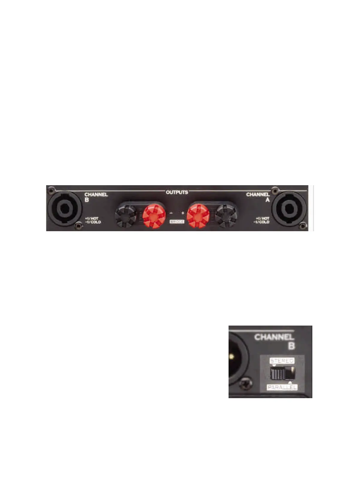
6 - CONNECTION IN STEREO MODE
First make sure that the BRIDGE OFF/ON mode
selector, located in the input section between the two
connection points is in the OFF position. Also make sure
that the STEREO/PARALLEL mode is in the STEREO
position.
There are two speaker output connectors. CH A for the left channel and CH B for the
right channel, both are fitted with Speakon type connectors, or Terminal connectors.
Each Speakon connector has 4 terminal points labeled as +1, -1, +2 and -2. Only use
the pins +1 for the Positive pole, and -1 for the Negative pole. Use a 1.5 Allen key to
firmly attach the cable (maximum section 4mm).